The couplingcapacitor removes the high voltage DC oset from the output signal of the tube
stage. This high-pass frequency is usually between 5-10 Hz, but if it is set higher then a user can
change the tonal and dynamic properes of the stage.
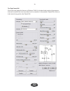
The gridresistor value is an all-in-one resistor used to calculate the eects of the stage’s band pass
limitaon. Inside each tube there is an internal capacitance called “Miller capacitance.” The
greater the resistor, the lower the bandwidth. The bandwidth can be calculated at 1/(6.28*RC)
where R is the “grid resistor” and C is the Miller capacitance (usually around 150pF). In a normal
triode stage with a 12AX7 tube, the bandwidth is around 15 kHz if the grid resistor is 68 kOhm.
The slider for ClassA/B is used for pentodes in push-pull conguraon only. (The Bias voltage
slider can be used as an alternave.) This sets the bias of the tube stage such that it corresponds
more to a Class A or B stage.
Some of the non-physical tweaks:
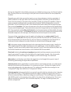
Normally, a tube’s output swing is determined by the VPP, along with the various loads in the
cir cuit. Seng ClipLimit to something higher than 1.0 gives the circuit a greater dynamic range.
The output gets higher and the distoron on one side decreases. Clipsoness is used to smooth
out the sharp dynamic edge and gives the distoron a smooth sound.
The default value of the DynamicBiasosetamount is 1.0, and scaling this value changes the
dynamics of the signal. The signal is usually not enrely free to move through the tube, and strong
transients and high volumes aect the bias of the tube, moving up and down, as a funcon of
volume.
Cathodebiasedtrebleboost (where applicable) changes the “lter eect” that the cathode
resistor & capacitor has on the frequency response.
The Biasadjust slider simply adds or subtracts a certain voltage to or from the tube’s bias. Other-
wise, this bias is dened by the tube and its surrounding components.
Extrainputheadroom gives the stage more dynamic headroom, making the tube distort later if
given a greater headroom. For a triode this means the signal is “aenuated” before the input and
“amplied” aer the output, thus restoring the signal strength to the following tube.
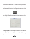
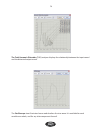
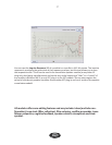
The tube Tweak GUI features the following graphical displays: A “bode plot” (frequency& phase
response) an oscilloscope (with input and output signal display overlaid) and “transfer funcon”
(a snapshot of the stac input-to-output relaonship).
The whole tube component can be disabled via the Disablecircuit checkbox.
40


