


1515
1515
15
ENGLISH
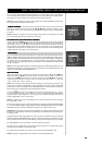
The T 752 receiver employs a simple, self-explanatory system of on-screen display "menus" that will appear
on the connected video monitor/TV. These are required during the setup process (and are useful in day-to-
day operation), so be sure to connect the monitor/TV before proceeding with setup.
NOTE: The on-screen displays are carried on both the S-Video and composite MONITOR OUT jacks, but are
not incorporated into the component-video output.
Press any of the HTR 2 remote's central cursor keys ([
<<
<<
<], [
∧∧
∧∧
∧], [
>>
>>
>], [
∨∨
∨∨
∨], and [Enter]) to display the T 752’s
main <Setup> menu on your video monitor/TV. If the OSD does not appear, check your MONITOR OUT
connections.
NOTE: The OSD does not appear on the T 752's component-video output, nor does it appear on the VIDEO
3 and 4 record-outputs; these are for recording, not monitoring.
NANA
NANA
NA
VIGAVIGA
VIGAVIGA
VIGA
TING THE OSD AND MAKING CHANGESTING THE OSD AND MAKING CHANGES
TING THE OSD AND MAKING CHANGESTING THE OSD AND MAKING CHANGES
TING THE OSD AND MAKING CHANGES
Use the HTR 2 remote's [
∧∧
∧∧
∧/
∨∨
∨∨
∨] keys to move up or down among the Setup menu's list of items; use [Enter]
to select a menu item, and use [
< <
< <
< /
>>
>>
>] to change the parameter-value (setting) of any item. Selecting the
<Save and Exit> returns "up" to the <Setup> menu while saving any parameter-value changes to the T 752’s
memory; selecting <Do Not Save and Exit> also returns to the main <Setup> menu, but abandons any
changes made on the previous menu. Selecting <Exit> from the main Setup menu exits the OSD altogether,
retaining parameter-value changes, if any, made previously.
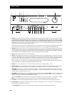
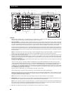
The T 752 is equipped with eight configurable inputs: six audio-video inputs labeled DVD, SAT, VCR, and
VIDEO4-6 (including VIDEO 6 on the front panel), and two audio-only inputs labeled CD and DISC. These are
flexibly configurable: For each labeled video input-jack position (DVD, SAT, VCR, VIDEO4-6) as displayed on
the <Video In> line of the <Input Settings> menu, you may freely assign: an analog audio input selected on
the <Audio In> line; and a digital input selected on the <Digital In> line. These will become active whenever
that input is selected.
NOTE: An incoming digital signal present at the assigned digital input will always take precedence over the
assigned analog-audio input, even if both are present. The digital signal can be temporarily selected “OFF”
using the front panel DIGITAL AUDIO SELECTOR button.
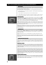
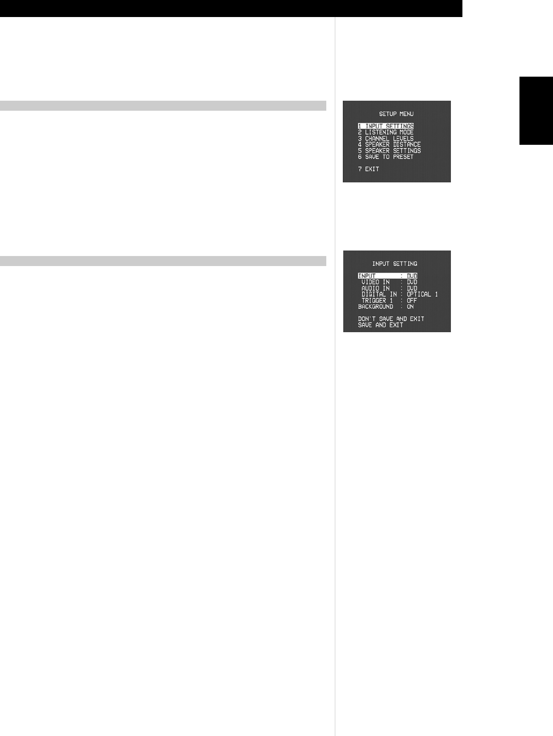
INPUT SETTINGSINPUT SETTINGS
INPUT SETTINGSINPUT SETTINGS
INPUT SETTINGS
From the main <Setup> menu, select the <Input settings> menu item using the HTR 2 remote's [
∧∧
∧∧
∧/
∨∨
∨∨
∨], and
[Enter] keys. Using the [
< <
< <
< /
>>
>>
>] keys select the video input (DVD, SAT, VCR, VIDEO 1-6) you wish to
configure. Use the [
∧∧
∧∧
∧/
∨∨
∨∨
∨] keys to move to the <Audio In> line, and then use the [
< <
< <
< /
>>
>>
>] keys to select the
analog audio input you wish to be linked to that input (usually, this will be the same, i.e., “DVD” with
“DVD,” “Video 4” with “Video 4,” and so on).
NOTE: It is not necessary to have an analog audio input connected for every video input you employ. In fact,
in some cases—for example for a DVD player—it may be preferable to make only a coaxial or optical digital
audio link to the T 752 for audio playback. This avoids possible confusion, and ensures that the T 752’s high-
performance surround and digital audio circuitry will always be employed.
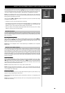
Now use the [
∧∧
∧∧
∧/
∨∨
∨∨
∨] keys to move to the <Digital In> line and select the digital input (“Opt 1-2,” “Coax 1-
4”) you wish linked to that input. If you set <Digital In> to “Off,” no incoming digital signal will be selected
by that input. (Set an input’s <Digital in> to “Off” only if you wish to ensure that that input will not play an
incoming digital bitstream, even if one is present.)
NOTE: The <Trigger Out:> line of the <Input Settings> menu is used to configure the T 752’s 12-volt trigger.
See “Trigger Setup,” below.
The component-video inputs are not configurable. Selecting the DVD input routes the COMPONENT VIDEO
IN 1 to the COMPONENT VIDEO OUT jacks; selecting SAT routes COMPONENT VIDEO IN 2 to the COMPO-
NENT VIDEO OUT jacks. Note that the OSD does not appear on the component-video output.
NOTE THAT: The combination of analog-audio input and digital input assigned above will always be recalled
whenever that input is selected via the front-panel VIDEO key, or the HTR 2 remote’s input-select keys, or
by recalling a Preset;
The digital and analog audio inputs assigned to a video input can be overridden by using the front-panel
AUDIO and DIGITAL AUDIO SELECTOR keys; however, the assigned input will return whenever that video
input is reselected, either via the front panel VIDEO key or using the HTR 2’s input-select keys (or a Preset);
The TAPE MONITOR loop is not configurable, and will not appear in the rotation;
Any audio input and any digital input may be configured with any video input, and the same analog and/or
digital inputs may be assigned to multiple video inputs;
The analog audio input selected on the <Audio In> line is also routed to the TAPE OUT jacks.
NOTE: That signals from digital inputs are not available on the analog TAPE OUT jacks.
ABOUT THE ON-SCREEN DISPLAYS (OSD) AND FRONT-PANEL READOUT
DISPLADISPLA
DISPLADISPLA
DISPLA
Y THE OSDY THE OSD
Y THE OSDY THE OSD
Y THE OSD
INPUT SETUPINPUT SETUP
INPUT SETUPINPUT SETUP
INPUT SETUP