


8
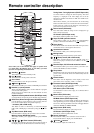
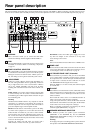
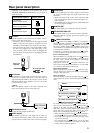
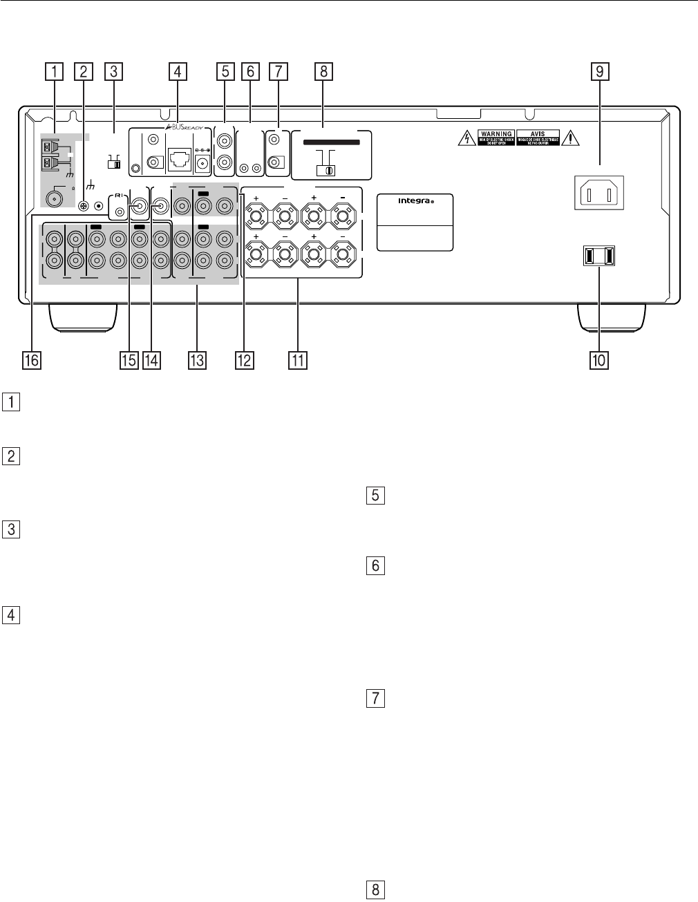
Rear panel description
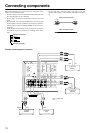
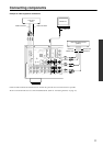
This section identifies and explains how to use the terminals found on the rear of the DTM-5.3. Before connecting your audio and video compo-
nents, be sure to read this section carefully and then proceed to the explanations on how to connect each individual component (see page 10).
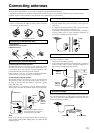
ANTENNA
These connectors enable you to connect the FM indoor
antenna and AM loop antenna supplied with the DTM-5.3.
GND
Use this GND terminal to connect the ground (or earth) wire if
a turntable is connected. Refer to “Connecting components”
on page 10.
ZONE 2 CONTROL SELECTOR
This switch enables you to select whether the Zone 2 function
is controlled from the A-BUS system or from the IR system.
Sliding the switch to the left will select A-BUS system con-
trol, and sliding it to the right will select IR system control.
A-BUS READY
A-BUS is a simple, efficient, elegant audio distribution sys-
tem. The wiring installation time is significantly reduced as
only a single CAT-5 wire is run to each location. A-BUS is
easy to use, reliable, affordable, and most of all, far better
sounding than conventional auto former based volume con-
trols.
ZONE 2 OUT: Use a CAT-5 (eight conductor twisted) cable
to connect directly from the receiver’s A-BUS RJ45 Hub to
an A-BUS keypad. A-BUS outputs enable connection of up to
four A-BUS keypads.
Warning:
DO NOT connect ZONE 2 OUT to any computer or network
connections (i.e., Ethernet). It will damage the computer or
network components since 24-volt power runs on this cable to
power the amplifier stages of the amplifier module.
IR OUT: Another feature of the A-BUS system is the ability
to control source equipment in a room other than where the
A-BUS module is installed. If you wish to control another
source from the receiver at the A-BUS keypad by remote con-
trol, connect the A-BUS or another brand IR emitter on the
receiver’s 40 K terminal. Then place the emitter on the remote
receiver on the front panel.
Typically, the emitter will work when you connect with a
40 K connector. If it does not work, try a 56 K connector.
DC INPUT: Connect the A-BUS power supply. Do not use
any other AC Adapter on this connector as it may cause
severe damage to the receiver.
Note:
Don’t insert an A-BUS connector while Zone 2 or DTM5.3 is on.
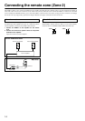
ZONE 2 OUT
Connect the device that will be used in the remote zone (Zone
2). For more information on making the connections, refer to
“Connecting the remote zone (Zone 2)” on page 14.
12V TRIGGER ZONE 2 OUT, IN terminal
These terminals are provided so that you can use the DTM-
5.3 to control another externally-connected device. Connect
the component to this 1/8-inch mini-jack terminal. When the
set input source is selected, the device will turn on. Set the
12V TRIGGER terminal using the Zone 2 mode.
When the DTM-5.3 is in Zone 2 mode, this terminal outputs
at 12 V/100 mA.
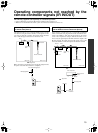
IR IN/OUT
If the DTM-5.3 is located inside a rack or cabinet that will not
allow infrared beams to reach the IR sensor, you will need to
connect a remote sensor to IR IN input to be able to use the
remote controller.
Then install the remote sensor in an unblocked location at
which you can easily point the remote controller.
Using a mini-jack connector, connect the IR emitter to the IR
OUT terminal on the DTM-5.3 and then place the IR emitter
on the remote sensor of the component or facing it.
Refer to “Operating components not reached by the remote
controller signals (IR IN/OUT)” on page 15.
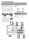
SPEAKER IMPEDANCE SELECTOR
The DTM-5.3 provides two speaker system connections
(SPEAKER A and SPEAKER B). Set the SPEAKER
IMPEDANCE SELECTOR according to the impedance of
speakers to be connected.
Warning:
Do not plug in the power cord during speaker system connection
and operation of the SPEAKER IMPEDANCE SELECTOR.
REMOTE
CONTROL
ANTENNA
OUT
AC OUTLET
AC 120
V 60
Hz SWITCHED
120
W 1
A
MAX.
AV RECEIVER
2.8
A
MODEL NO. DTM
-
5.3
RATING:
AC 120
V 60
Hz
AC
INLET
A
B
IN
IN
IN
IN
OUT
IN
IN
OUT
OUTOUT
A + B
:
8 OHMS MIN.
/SPEAKER
A OR B
:
8 OHMS MIN.
/SPEAKER
A OR B
:
4 OHMS MIN.
/SPEAKER
FM
75
GND
ZONE 2
CONTROL
SELECTOR
IR OUT 40K
IR OUT
56K
ZONE 2
OUT
DC IN
24V 1A
IN
OUT
12
V
TRIGG
E
R
IR
OUT
ZONE 2
SPEAKERS
VIDEO
DVD
MONITOR
OUT
PHONO
CD
TAPE 1
TAPE 2
VIDEO
DVD
V
R
L
R
L
A-BUS
IR
AM
R
L
SET BEFORE POWER ON
SPEAKER
IMPEDANCE
SELECTOR
ZONE 2
OUT
IN
R
L
SUBWOOFER
PRE OUT
IN
IN
A
B