


15
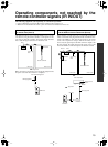
Operating components not reached by the
remote controller signals (IR IN/OUT)
The following equipment (sold separately) is essential for operation:
• Onkyo’s Multi-Room System kits (IR Remote Controller Extension System), or
• Multiroom A/V distribution and control systems from Niles
®
and Xantech
®
to name a few.
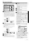
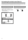
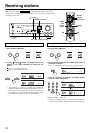
Controlling the DTM-5.3 in the main room from
a remote zone (Zone 2)
The IR IN input allows you to control the DTM-5.3 from a remote
zone (Zone 2) using the remote controller, even though the remote
zone may be physically separated. The diagram below illustrates
how to make the proper connections for the remote zone.
Make connection as shown below. Do not plug the equipment into
the power source until the connection is completed.
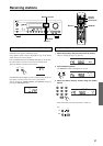
Controlling another component in the main room
via the DTM-5.3 from a remote zone (Zone 2)
In this situation, you will need to use a commercially-available IR
emitter. Connect the mini plug of the IR emitter to the IR OUT ter-
minal on the DTM-5.3. Then place the IR emitter on the remote
sensor of the component or facing it. When the IR emitter is con-
nected, only the signal input to the IR IN terminal is output to the
IR OUT terminal. The signal input from the remote sensor on the
front of the DTM-5.3 will not be output to the IR OUT terminal.
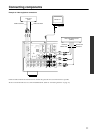
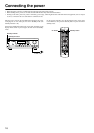
Connecting
block
DTM-5.3
Main room
: Signal flow
IR IN
Zone 2 room
IR Receiver
Remote controller
IN
OUT
IR
Mini plug cable
from connecting block
DTM-5.3
IN
OUT
IR
DTM-5.3
Remote control
sensor
other component
Emitter
Mini plug cable
: Signal flow
Mini plug
IR Emitter
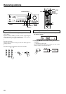
Connecting
block
DTM-5.3
Main room
: Signal flow
IR IN
Zone 2 room
IR Receiver
Remote controller
IR OUT
other
component
IR Emitter