


12
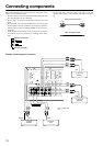
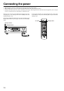
Connecting speakers
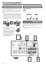
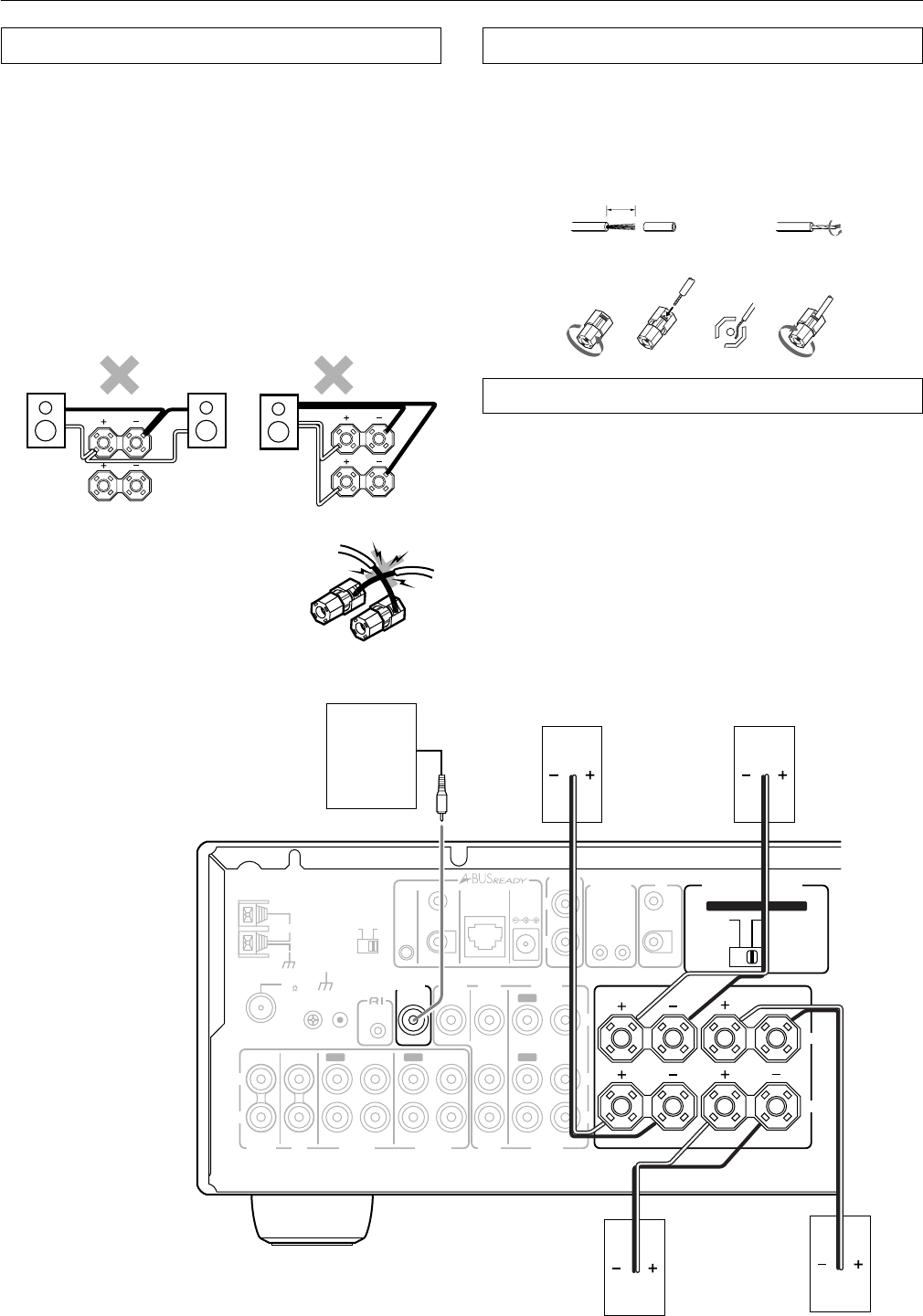
Connecting the speaker
You can connect two separate pairs of speaker systems.
Please connect each speaker according to the illustration, observing
the correct connections for R, L, + and –.
Check the speaker impedance, then set the SPEAKER IMPEDANCE
SELECTOR switch accordingly. Refer to pages 8 and 9 for details.
Notes:
• Do not use unnecessarily long or extremely thin speaker leads.
If the DC resistance of the speaker leads is too high, the damp-
ing factor will decrease, adversely affecting the sound quality.
• When you are using only one speaker or when you wish to lis-
ten to monaural (mono) sound, a single speaker should never be
connected in parallel to both the right and left-channel terminals
simultaneously.
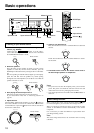
• To prevent damage to circuitry, never
short-circuit the positive (+) and nega-
tive (–) speaker wire.
• Be sure to connect the positive and nega-
tive cables for the speakers properly. If
they are connected to the wrong terminal,
the left and right signals will be reversed
and the audio will sound unnatural.
• Do not connect more than one speaker
cable to one speaker terminal. Doing so
may damage the DTM-5.3.
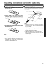
Connecting the speaker cable
1. Strip away 5/8 inch (15 mm) of wire insulation.
2. Twist wire ends very tight.
3. Unscrew.
4. Insert wire.
5. Screw.
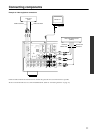
Connecting a subwoofer
Use the SUBWOOFER PRE OUT jack to connect a subwoofer
with a built-in power amplifier. If your subwoofer does not have a
built-in amplifier, connect an amplifier to the PRE OUT SUB-
WOOFER jack and the subwoofer to the amplifier.
Note:
The SUBWOOFER PRE OUT can only operate when speaker sys-
tem A is turned on.
B
SPEAKERS
R
L
B
SPEAKERS
R
L
NO
5/8 inch
(15 mm)
1
34 5
2
REMOTE
CONTROL
ANTENNA
OUT
A
B
IN
IN
IN
IN
OUT
IN
IN
OUT
OUT
A + B
:
8 OHMS MIN.
/SPEAKER
A OR B
:
8 OHMS MIN.
/SPEAKER
A OR B
:
4 OHMS MIN.
/SPEAKER
FM
75
GND
ZONE 2
CONTROL
SELECTOR
IR OUT 40K
IR OUT
56K
ZONE 2
OUT
DC IN
24V 1A
IN
OUT
12
V
TRIGG
E
R
IR
OUT
ZONE 2
SPEAKERS
VIDEO
DVD
MONITOR
OUT
PHONO
CD
TAPE 1
TAPE 2
VIDEO
DVD
V
R
L
R
L
A-BUS
IR
AM
R
L
SET BEFORE POWER ON
SPEAKER
IMPEDANCE
SELECTOR
ZONE 2
OUT
IN
R
L
SUBWOOFER
PRE OUT
IN
IN
A
B
Subwoofer
SPEAKER A
SPEAKER B
Left ch.
Right ch.
Left ch.
Right ch.