


10
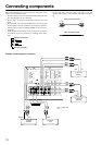
Connecting components
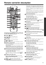
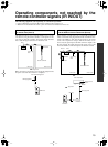
This section explains how to connect the main components to the
DTM-5.3 in the standard manner.
• Be sure to always refer to the instruction manual that came with
the component that you are connecting.
• Do not plug in the power cord until all connections have been
made.
• For input jacks, red connectors (marked R) are used for the right
channel, white connectors (marked L) are used for the left chan-
nel, and yellow connectors (marked VIDEO) are used for video
connection.
• Insert all plugs and connectors securely. Improper connections
can result in noise, poor performance, or damage to the equip-
ment.
• Do not bind audio connection cables with power cords and
speaker cables. Doing so may adversely effect the sound qual-
ity.
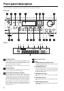
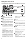
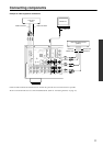
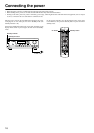
Example of audio equipment connection
Improper connection
Inserted completely
R (Right) R
L (Left) L
Audio connection cable
Video connection cable
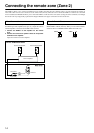
REMOTE
CONTROL
ANTENNA
OUT
IN
IN
IN
IN
OUT
IN
IN
OUT
OUTOUT
FM
75
GND
ZONE 2
CONTROL
SELECTOR
IR OUT 40K
IR OUT
56K
ZONE 2
OUT
DC IN
24V 1A
OUT
ZONE 2
VIDEO
DVD
MONITOR
OUT
PHONO
CD
TAPE 1
TAPE 2
VIDEO
DVD
V
R
L
A-BUS
IR
AM
R
L
R
L
SUBWOOFER
PRE OUT
IN
IN
A
B
INOUT
Tape Deck
(TAPE 1)
Turntable
(PHONO)
CD Player
(CD)
OUT
Ground
: signal flow
Tape Deck
(TAPE 2)
OUT
INOUT