


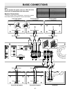
-E11-
C
R
/P
R
C
B
/P
B
Y
COMPONENT
VIDEO OUT
R
L
VIDEO 2VIDEO 1
T
VIDEO IN
AUDIO IN
R
L
VIDEO IN
AUDIO IN
VIDEO OUT
AUDIO OUT
VIDEO
S-VIDEO
(DVD ONLY)
MONITOR OUT
R L CENTER
FRONT
RL
SUB WOOFER
SURROUND
SPEAKERS 8Ω
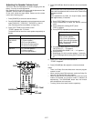
VIDEO OUT SELECT
(DVD ONLY)
S-VIDEOCOMPONENT
VIDEO OUT
SCAN SELECT
SELECTABLE INTERLACE
34
CH.
TO TV ANT. IN
R-AUDIO-LVIDEO
A/V INPUT JACKS
VHF/UHF
ANTENNA
IN
3
1
2
C
R
/P
R
C
B
/P
B
Y
COMPONENT
VIDEO OUT
R
L
VIDEO 2VIDEO 1
ANT
FM
75Ω
AM
LOOP
VIDEO IN
AUDIO IN
R
L
VIDEO IN
AUDIO IN
VIDEO OUT
AUDIO OUT
VIDEO
S-VIDEO
(DVD ONLY)
MONITOR OUT
R L CENTER
FRONT
RL
SUB WOOFER
SURROUND
SPEAKERS 8Ω
VIDEO OUT SELECT
(DVD ONLY)
S-VIDEOCOMPONENT
VIDEO OUT
SCAN SELECT
SELECTABLE INTERLACE
34
CH.
TO TV ANT. IN
R-AUDIO-LVIDEO
A/V INPUT JACKS
VHF/UHF
ANTENNA
IN
VHF/UHF
FROM ANT.
IN
OUT
TO TV
IN OUT
34
LINE1(AUX1)
VIDEO
CH.
L
R
L
R
AUDIO
3
4
5
1
2
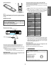
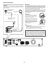
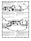
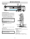
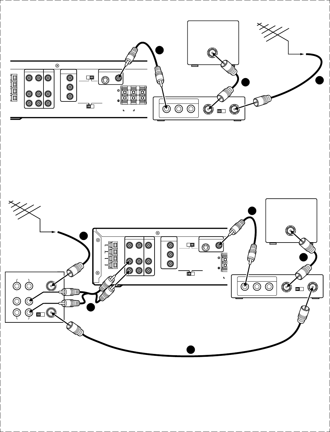
Using RF Modulator
If your TV does not have a Video input jack and has an antenna
terminal only, please purchase the *RF Modulator (not supplied).
(*Please consult your audio/video dealer.)
Example: Unit, TV and RF Modulator connections
1. Connect the antenna cable (not supplied) to the ANT. IN
terminal of the RF Modulator.
2. Connect the 75-ohm coaxial cable (not supplied) between
the TO TV terminal of the RF Modulator and the VHF/UHF
ANTENNA IN terminal of the TV.
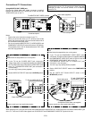
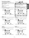
Example: Unit, VCR, TV and RF Modulator connections
1. Connect the antenna cable (not supplied) to the VHF/UHF
FROM ANT IN terminal of the VCR.
2. Connect the 75-ohm coaxial cable (not supplied) between
the TO TV OUT terminal of the VCR and the ANT. IN
terminal of the RF Modulator.
3. Connect the 75-ohm coaxial cable (not supplied) between
the TO TV terminal of the RF Modulator and the VHF/UHF
ANTENNA IN terminal of the TV.
4. Connect the audio cables (not supplied) between the VIDEO
1 AUDIO IN jacks of the unit and the AUDIO OUT jacks of
the VCR. Use the red connectors for the right-R jacks and
the white connectors for the left-L jacks.
5. Connect the Video cable with yellow connectors (supplied)
between the MONITOR OUT VIDEO jack of the unit and the
VIDEO input jack of the RF Modulator.
Note:
For more details, please refer to the instruction manual of the RF
Modulator.
3. Connect the Video cable with yellow connectors (supplied)
between the MONITOR OUT VIDEO jack of the unit and the
VIDEO input jack of the RF Modulator.
Note:
For more details, please refer to the instruction manual of the RF
Modulator.
To MONITOR OUT VIDEO (Yellow)
To MONITOR OUT VIDEO (Yellow)
Partial back panel
Partial back panel
HiFi Stereo VCR
RF Modulator
RF Modulator
TV's back panel
TV's back panel