


-E10-
ENGLISH
C
R
/P
R
C
B
/P
B
Y
COMPONENT
VIDEO OUT
R
L
VIDEO 2VIDEO 1
VIDEO IN
AUDIO IN
R
L
VIDEO IN
AUDIO IN
VIDEO OUT
AUDIO OUT
VIDEO
S-VIDEO
(DVD ONLY)
MONITOR OUT
R L CENTER
FRONT
RL
SUB WOOFER
SURROUND
SPEAKERS 8Ω
VIDEO OUT SELECT
(DVD ONLY)
S-VIDEOCOMPONENT
VIDEO OUT
SCAN SELECT
SELECTABLE INTERLACE
COMPONENT VIDEO INPUT
YCBCR
2
3
1
C
R
/P
R
C
B
/P
B
Y
COMPONENT
VIDEO OUT
R
L
VIDEO 2VIDEO 1
ANT
FM
75Ω
AM
LOOP
VIDEO IN
AUDIO IN
R
L
VIDEO IN
AUDIO IN
VIDEO OUT
AUDIO OUT
VIDEO
S-VIDEO
(DVD ONLY)
MONITOR OUT
R L CENTER
FRONT
RL
SUB WOOFER
SURROUND
SPEAKERS 8Ω
VIDEO OUT SELECT
(DVD ONLY)
S-VIDEOCOMPONENT
VIDEO OUT
SCAN SELECT
SELECTABLE INTERLACE
S-VIDEO IN 1
R-AUDIO-L
R
L
VIDEO
AUDIO
VIDEO
INPUT
1
AUDIO
OUTPUT
R-AUDIO-L VIDEO
AUDIO
VIDEO
INPUT
2
VIDEO
S-VIDEO
(DVD ONLY)
MONITOR OUT
R L CENTER
FRONT
RL
SUB WOOFER
SURROUND
SPEAKERS 8Ω
VIDEO OUT SELECT
(DVD ONLY)
S-VIDEOCOMPONENT
VIDEO OUT
SCAN SELECT
SELECTABLE INTERLACE
S-VIDEO IN 1
R-AUDIO-L
R
L
VIDEO
AUDIO
VIDEO
INPUT
1
AUDIO
OUTPUT
R-AUDIO-L VIDEO
AUDIO
VIDEO
INPUT
2
1
2
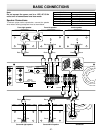
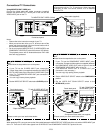
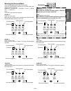
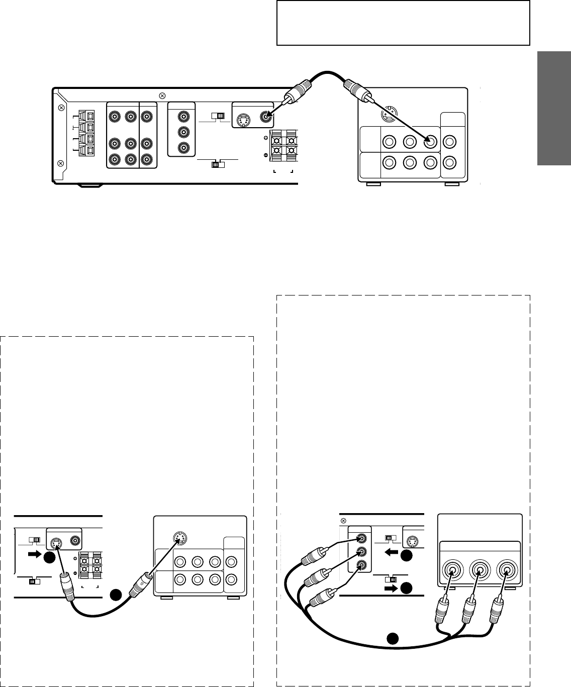
Conventional TV Connections
Using MONITOR OUT VIDEO jack
Connect the Video cable with yellow connectors (supplied)
between the MONITOR OUT VIDEO jack of the unit and the
VIDEO INPUT jack on the TV.
Notes:
• Please refer to the instruction manual of your TV.
• When you connect the unit to your TV, be sure to turn off the
power and disconnect both units from the wall outlet until all
the connections have been made.
• Do not connect the MONITOR OUT (S-VIDEO/VIDEO) and
COMPONENT VIDEO OUT jacks of the unit to a VCR directly.
The playback picture will be distorted because DVD video
discs are copy protected.
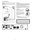
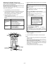
Using MONITOR OUT S-VIDEO jack
Note:
Please follow the steps before turn on the power.
1. If your TV has the S-VIDEO INPUT jack, connect the
*Super-Video cable (not supplied) between the MONITOR
OUT S-VIDEO jack of the unit and the S-VIDEO INPUT jack
of the TV. (The MONITOR VIDEO OUT jack connection is
not necessary.)
You can enjoy clearer picture playback.
2. Set the VIDEO OUT SELECT switch to the S-VIDEO position.
*Please consult your local audio/video dealer.
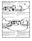
Using COMPONENT VIDEO OUT jacks
Note:
Please follow the steps before turn on the power.
1. If your TV has the COMPONENT VIDEO INPUT jacks,
connect the *Component Video cable (not supplied) between
the COMPONENT VIDEO OUT jacks of the unit and the
COMPONENT VIDEO INPUT jacks of the TV.
(The MONITOR VIDEO OUT or S-VIDEO OUT jack
connection is not necessary.)
You can enjoy high quality picture playback.
2. Set the VIDEO OUT SELECT switch to the COMPONENT
position.
3. Set the VIDEO OUT SCAN SELECT switch to the
INTERLACE position.
*Super-Video cable (not supplied)
TV with S-VIDEO INPUT jackPartial back panel
Partial back panel
TV with COMPONENT
VIDEO INPUT jacks
*Component Video cable (not supplied)
*Please consult your local audio/video dealer.
TV's back panel
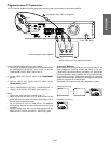
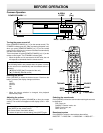
Important Information:
To connect the unit to a TV, TV must have a Video input jack
(RCA-type) at least. You cannot connect it to an antenna
terminal of TV.
Note:
When watching VCR, you must connect the Video cable between the MONITOR OUT VIDEO jack of the unit and the VIDEO INPUT jack
of the TV. There are no VCR video signals from S-VIDEO OUT and COMPONENT VIDEO OUT jacks of the unit.
Video cable (supplied)
To VIDEO
INPUT
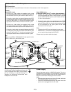
Red
Blue
Green
Green
Blue
Red
To MONITOR OUT VIDEO (Yellow)
Partial back panel