


1-4
Mini Controller User’s Manual
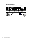
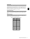
Mini Controller Switch Settings
The DIP switches on the Mini Controller must be properly set so the controller can
send the correct data packets to the number of available fixtures. If power has
already been applied to the controller, the seven-segment LEDs will blink
CF
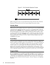
(configure) until a DIP switch is set. The DIP switches are located on the front
panel of the Mini Controller in the lower right-hand corner. Refer to Figure 1.1.
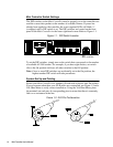
Figure 1.1. DIP Switch Location
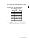
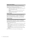
To set the DIP switches, simply turn on the switch that corresponds to the number
of available AF1000 strobes. For example, if you have eight strobes, set switch
<
8
> to the On position and leave all other switches in the Off position.
Note: if two or more DIP switches are accidentally set to the On position, the
highest number DIP switch will take precedence.
System Set Up and Cabling
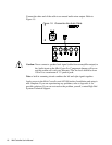
Secure your Mini Controller in a standard 19-inch rack or place it on a flat surface.
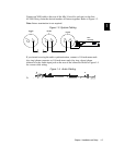
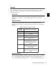
If you are unsure about how your XLR cables are constructed, use Figure 1.2 and a
Volt Ohm Meter to verify correct installation. Using the Volt Ohm Meter, place
the terminals on each pair of corresponding pins to ensure that there is extremely
little or no resistance in the line.
Figure 1.2. XLR Pin Configuration
DIP switches