


INSTALLATION AND CONNECTIONS 15
INSTALLATION AND CONNECTIONS
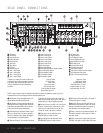
Jacks ‚⁄›fion the rear panel. The Audio
and Video Record/In jacks on the VCR should be
connected to the
Video 1 or Video 2 Out Jacks
‹fl‡ on the DPR 1001.
2. Connect the analog audio and video outputs of a
television set or any other video source to the
Video
2 Input Jacks
›fi.
3. Connect the analog audio and video outputs of a
satellite receiver,cable TV converter or any other
video source to the
Video 3 Jacks °·.
4. Connect the analog audio and video outputs of
a DVD or laser disc player to the
DVD Jacks
a .When a digital audio connection is used
for your DVD player,the default connection is
the
Coaxial 1 Digital Audio Input Jack k.
However,the connection may also be made to any
of the
Optical K or Coaxial kM digital
audio inputs, provided that the digital input source
selection is changed as shown on pages 18 and
27. If your DVD or DVD-Audio player includes an
onboard surround decoder and 6- or 8-channel
line-level audio outputs, you may connect these
audio outputs to the
6- and 8-Channel Direct
Inputs
as appropriate.When you wish to
hear this decoded audio, select the DVD input first in
order to select the video signal from the DVD player,
then select the 6- or 8-Channel Direct Input source
for the audio.
5. Connect the digital audio outputs of a DVD player,
satellite receiver,cable box or HDTV converter to the
appropriate
Optical or Coaxial Digital Inputs
k KM.
6. Connect the
Video Monitor Output jacks on
the receiver to the composite or S-Video input of
your television monitor or video projector.
7. If your DVD player and monitor both have
component video connections, connect the
component outputs of the DVD player to the
DVD Component Video Inputs . Even when
component video connections are used, the audio
connections should still be made to either the analog
DVD Audio Inputs a or any of the Optical or
Coaxial Digital Input Jacks k KM.
8. If another component video device is available,
connect it to the
Video 2 Component Video Input
Jacks
.The audio connections for this device
should be made to either the
Video 2 Audio Input
Jacks
fi or any of the Optical or Coaxial Digital
Input Jacks
k KM
.
9. If the component video inputs are used, connect the
Video Monitor Component Video Outputs to
the component video inputs of your TV,projector or
display device.
10. If you have a camcorder, video game or other
audio/video device that is connected to the receiver
on a temporary rather than permanent basis, con-
nect the audio, video and digital audio outputs of that
device to the
Video 4 Front Panel Inputs N.A
device connected here is selected as the Video 4
input, and the digital inputs must be assigned to the
Video 4 input. (See pages 18 and 27 for more
information on input configuration.)
VIDEO CONNECTION NOTES:
• When the component video jacks are used, the on-
screen menus are not visible and you must switch to
the standard composite or S-Video input on your TV
to view them.
• The DPR 1001 will accept either standard composite,
S-Video or Y/Pr/Pb component video signals. How-
ever,it will not convert composite or S signals to
component video.
• Component or composite video signals may only be
viewed in their native formats.
System and Power Connections
The DPR 1001 is designed for flexible use with multi-
room systems, external control components and power
amplifiers.
Main Room Remote Control Extension
If the receiver is placed behind a solid or smoked glass
cabinet door,the obstruction may prevent the remote
sensor from receiving commands. In this event, an
optional remote infrared (IR) sensor may be used.
Connect the output of the remote sensor to the
Remote
IR Input Jack
∞.
If other components are also prevented from receiving
remote commands, only one sensor is needed. Simply
use this unit’s sensor or a remote eye by running a con-
nection from the
Remote IR Output Jack ¢ to the
remote IR input jack on Harman Kardon (or other com-
patible) equipment.
Multiroom IR Link
The remote room IR receiver should be connected to
the DPR 1001 via standard coaxial cable. Plug the IR
connection cable into the
Multiroom IR Input Jack £
on the DPR 1001’s rear panel.
If other Harman Kardon-compatible source equipment is
part of the main room installation, the
Remote IR
Output Jack
¢ on the rear panel should be con-
nected to the IR IN jack on the source equipment.This
will enable the remote room location to control source
equipment functions.
NOTE: All remotely controlled components must be
linked together in a “daisy chain”. Connect the
IR OUT
jack of one unit to the IR IN of the next to establish
this chain.
Multiroom Audio Connections
Depending on the distance from the DPR 1001 to
the remote room, three options are available for audio
connection:
Option 1: Run high-quality, shielded audio interconnect
cable from the DPR 1001 to the
remote room. In the
remote room, connect the interconnect cable to a stereo
power amplifier.The amplifier
will be connected to the
room’s speakers.At the DPR 1001, plug the audio inter-
connect cables into the
Multiroom Output Jacks ª
on the DPR 1001’s rear panel.
Option 2: Connect the Multiroom Output Jacks ª
on the DPR 1001 to the inputs of an optional stereo
power amplifier that is located with the DPR. Run high-
quality speaker wire from the amplifier to the speakers in
the remote room.
Option 3: When only a 5.1-channel system is required
for the main listening area, the
Surround Back
Speaker Outputs
c may be configured for use in the
second zone of a multiroom system. Run high-quality
speaker wire from the
Surround Back Speaker
Output
c terminals on the DPR 1001 to the speakers
in the remote room.Then, follow the instructions on
page 20 for using the DPR 1001’s on-screen menu
system to configure the
Surround Back Speaker
Outputs
c for operation in the remote room.
NOTE: In all of these options, you may connect an
optional IR sensor in the remote room to the DPR 1001
via an appropriate cable. Connect the sensor’s cable to
the
Multiroom IR Input £ on the DPR 1001 and use
the Zone II remote to control the room volume.Alter-
natively, you may install an optional volume control
between the output of the amplifier or
Surround Back
Speaker Outputs
c and the speakers.
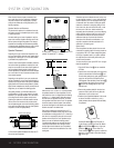
AC Power Connections
This unit is equipped with two AC Accessory Outlets
g.They may be used to power accessory devices,
but they should not be used with high-current draw
equipment such as power amplifiers.The total power
draw for both outlets may not exceed 100 watts.
The top outlet is unswitched, which means that power is
available as long as the DPR is plugged in.
The bottom outlet is switched, which means that power
is supplied only when the DPR is turned on. Since the
power is removed when the DPR is turned off,this outlet
should not be used for devices such as VCRs where a
constant power source is required for a clock or timer,or
for products that do not have a mechanical power switch
and thus turn off when AC power is removed.
Finally, when all connections are complete,plug the
power cord into a nonswitchedAC wall outlet.You’re
almost ready to enjoy the DPR 1001!
36
31
38
31
37
35
31
34
33
31
32
12