


14 INSTALLATION AND CONNECTIONS
INSTALLATION AND CONNECTIONS
System Installation
After unpacking the unit, and placing it on a solid surface
capable of supporting its weight, you will need to make
the connections to your audio and video equipment.
IMPORTANT NOTE: For your personal safety and to
avoid possible damage to your equipment and speakers,
it is always a good practice to turn off and unplug the
DPR 1001 and ALL source equipment from the AC
output before making any audio or video system
connections.
Audio Equipment Connections
We recommend that you use high-quality interconnect
cables when making connections to source equipment
and recorders to preserve the integrity of the signals.
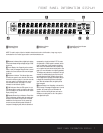
1. Connect the analog output of a CD player to the
CD Inputs •.
NOTE: If your CD player has both fixed and variable
audio outputs, it is best to use the fixed output unless
you find that the input to the receiver is so low that the
sound is noisy, or so high that the signal is distorted.
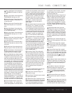
2. Connect the analog Play/Out jacks of a cassette
deck, MD,CD-R or other audio recorder to the
Tape Inputs §.Connect the analog Record/In
jacks on the recorder to the
Tape Outputs ¶
on the DPR 1001.
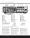
3. Connect the output of any digital sources such as a
CD or DVD changer or player,video game, a digital
satellite receiver,HDTV tuner or digital cable set-top
box or the output of a compatible computer sound
card to the
Optical or Coaxial Digital Inputs
k KM.
4. Connect the coaxial or optical
Digital Audio
Outputs
b on the rear panel of the DPR 1001
to the matching digital input connections on a
CD-R or MiniDisc recorder.
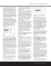
5.Assemble the AM Loop Antenna supplied with the
unit so that the tabs at the bottom of the antenna
loop snap into the holes in the base. Connect the
wires from the
AM antenna to the Antenna
Terminals
™.Make certain to connect the wire
marked GND to the top terminal screw.
6. Connect the supplied FM antenna to the
FM
Antenna
(75-ohm) Connection ¡.The FM
antenna may be an external roof antenna, an inside
powered or wire-lead antenna or a connection from
a cable TV system. If the antenna or connection
uses 300-ohm twin-lead cable, you must use an
optional 300-ohm-to-75-ohm adapter.
7. Connect the front, center, surround and surround
back speaker outputs
cdef to the respective
speakers.
To ensure that all the audio signals are carried to your
speakers without loss of clarity or resolution, we
suggest that you use high-quality speaker cable. Many
brands of cable are available and the choice of cable
may be influenced by the distance between your
speakers and the receiver, the type of speakers you
use, personal preferences and other factors. Your
dealer or installer is a valuable resource to consult
in selecting the proper cable.
Regardless of the brand of cable selected, we recom-
mend that you use a cable constructed of
multistrand
copper with a gauge of 14 or smaller.
Remember that
in specifying cable, the lower the number, the thicker
the cable.
Cable with a gauge of 16 may be used for short runs
of less than ten feet. We do not recommend that you
use cables with an AWG equivalent of 18 or higher,
due to the power loss and degradation in performance
that will occur.
Cables that are run inside walls should have the
appropriate markings to indicate listing with UL,
CSA or other appropriate testing agency standards.
Questions about running cables inside walls should be
referred to your installer or a licensed electrician who
is familiar with the NEC and/or the applicable local
building codes in your area.
When connecting wires to the speakers, be certain to
observe proper polarity. Note that the positive (+)
terminal of each speaker connection now carries a
specific color code as noted on page 8. However, most
speakers will still use a red terminal for the postive (+)
connection. Connect the “negative” or “black” wire to the
same terminal on both the receiver and the speaker.
NOTE: While most speaker manufacturers adhere
to an industry convention of using black terminals
for negative and red ones for positive, some
manufacturers may vary from this configuration. To
ensure proper phase and optimal performance, consult
the identification plate on your speaker or the speaker’s
manual to verify polarity. If you do not know the polarity
of your speaker,ask your dealer for advice before
proceeding, or consult the speaker’s manufacturer.
We also recommend that the length of cable used
to connect speaker pairs be identical. For example,
use the same length of cable to connect the front left
and front right, surround left and surround right, and
surround back left and surround back right speakers,
even if the speakers are at different distances from the
DPR 1001.
8. Connections to a subwoofer are normally made via
a line-level audio connection from the
LFE/Sub-
woofer Output
j to the LFE or line-level input of
a subwoofer with a built-in amplifier.When a passive
subwoofer is used, the connection first goes to a
power amplifier,which will be connected to one or
more subwoofer speakers. If you are using a pow-
ered subwoofer that does not have line-level input
connections, follow the instructions furnished with the
speaker for connection information.
9. If an external multichannel audio source with
5.1 outputs such as an external digital processor/
decoder, DVD-Audio or SACD player is used,
connect the outputs of that device to the
6-Channel Direct Inputs
.
10. If an external multichannel audio source with
7.1 outputs such as an external digital processor/
decoder, DVD-Audio or SACD player is used,
first connect the outputs of that device to the
6-Channel Direct Inputs , and then connect
the Surround Back Left and Surround Back Right
output channels of the source device to the
8-Channel Direct Inputs .
Video Equipment Connections
Video equipment is connected in the same manner
as audio components. Again, the use of high-quality
interconnect cables is recommended to preserve
signal quality.
Although the outputs from any compatible video
device may be connected to any video input, to sim-
plify programming device codes into the remote con-
trol, we recommend that a hard-drive recorder product
such as a TiVo
®
or ReplayTV
®
be connected to the
Video 1 Connectors ‚⁄ ‹. If there is no hard
-
drive recorder in your system, connect the VCR to
those connectors; otherwise connect it to the
Video 2
Connectors
›fifl‡
. The audio outputs of your
TV should be connected to the
Video 2 Input
Connector
fi
, and the outputs of a cable box or
satellite receiver to the
Video 3 Input Connectors
°·.
Note that the DPR 1001 will not convert signals from
composite to S-Video, or vice versa. S-Video inputs may
only be viewed when the DPR 1001 is connected to a
TV set or video display with S-Video capability. If you use
both standard composite video and S-Video sources in
your system, it is important that you connect both an
S-Video cable and a standard composite video cable
(a coax cable with an RCA plug on both ends) between
the DPR 1001 and your TV or projector.Consult the
instructions for your TV set or projector for more infor-
mation on connecting both types of signals.
1. Connect a VCR’s or other video source’s audio and
video Play/Out jacks to the
Video 1 or Video 2 In
12
34
33
33
31