


8 REAR PANEL CONNECTIONS
REAR PANEL CONNECTIONS
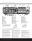
¡ FM Antenna: Connect the supplied indoor (or an
optional external) FM antenna to this terminal.
™ AM Antenna: Connect the AM loop antenna sup-
plied with the receiver to these terminals. Connect the
black antenna wire marked GND to the top terminal
screw on the DPR with the grounding symbol.
£ Multiroom IR Input: Connect the output of an IR
sensor in a remote room to this jack to operate the
DPR 1001’s multiroom control system. (See pages 31
for more information on multiroom systems.)
¢ Remote IR Output: This connection permits the
IR sensor in the receiver to serve other remote con
trolled devices. Connect this jack to the “IR IN” jack on
Harman Kardon (or other compatible) equipment.
∞ Remote IR Input: If the DPR 1001’s front panel
IR sensor is blocked due to cabinet doors or other
obstructions, an external IR sensor may be used.
Connect the output of the sensor to this jack.
§ Tape Inputs: Connect these jacks to the
PLAY/OUT jacks of an audio recorder.
¶ Tape Outputs: Connect these jacks to the
RECORD/INPUT jacks of an audio recorder.
• CD Inputs: Connect these jacks to the output of
a compact disc player or changer.
ª Multiroom Outputs: Connect these jacks to an
optional audio power amplifier to listen to the source
selected by the mulitroom system. (See page 31 for
more information on the multiroom system.)
‚ Video 1 Video Inputs: Connect these jacks to the
PLAY/OUT composite or S-Video jacks on a VCR or
other video source.
⁄ Video 1 Audio Inputs: Connect these jacks to the
PLAY/OUT audio jacks on a VCR or other video source.
∞
ª
‚
‹
fi
·
a
b
c
d
e
f
g
ii
j
‡
§
31
32
36
h
k
34
37
38
33
•
¶
⁄
¡
™
£
¢
°
›
fl
35
550W
SWITCHED 50W 0.5A MAX
SPEAKERS 8Ω
LFE/SUB
FR FL
LFE/
SUB
FR FL
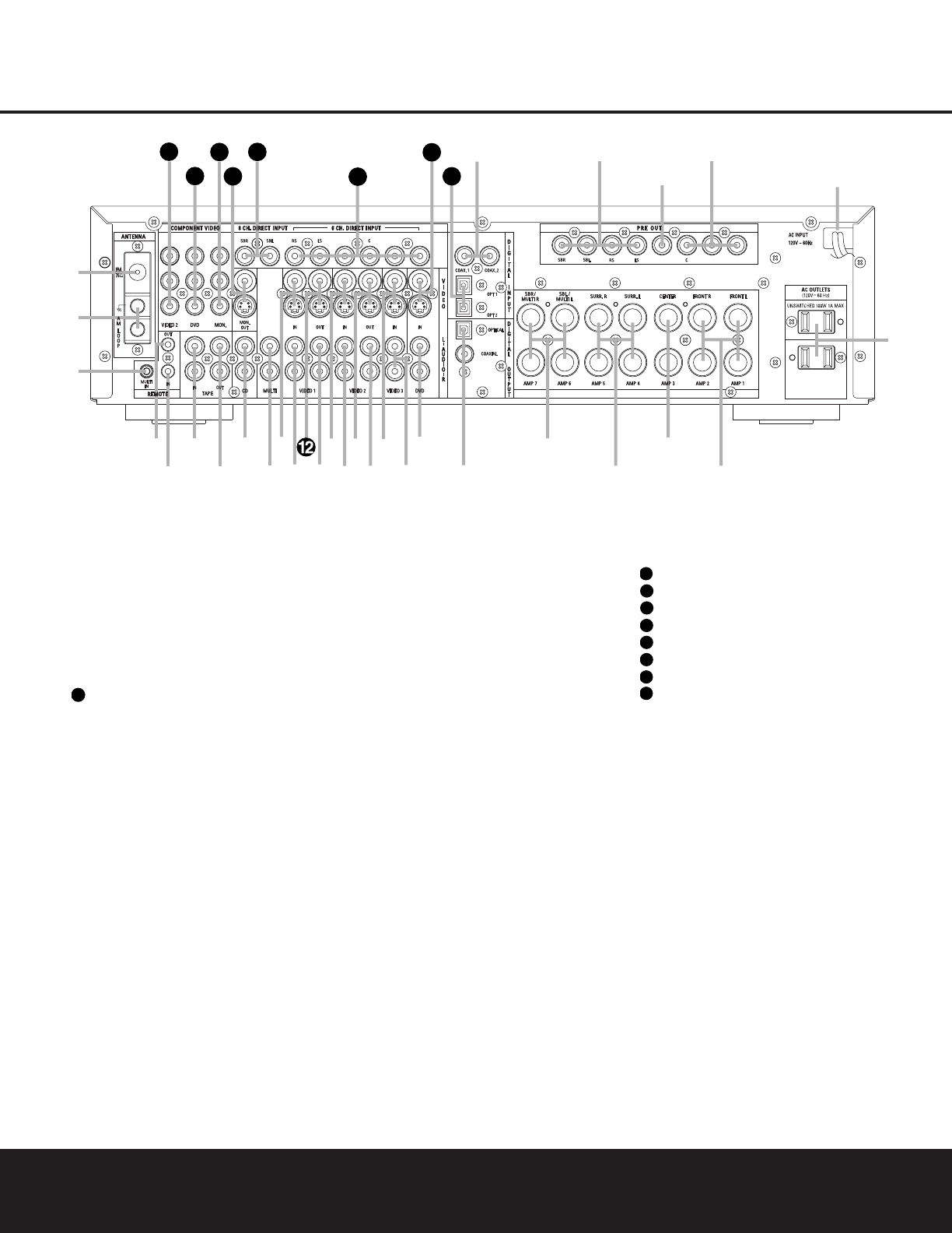
¡ FM Antenna
™ AM Antenna
£ Multiroom IR Input
¢ Remote IR Output
∞ Remote IR Input
§ Tape Inputs
¶ Tape Outputs
• CD Inputs
ª Multiroom Outputs
‚ Video 1 Video Inputs
⁄ Video 1 Audio Inputs
Video 1 Video Outputs
‹ Video 1 Audio Outputs
› Video 2 Video Inputs
fi Video 2 Audio Inputs
fl Video 2 Video Outputs
‡ Video 2 Audio Outputs
° Video 3 Video Inputs
· Video 3 Audio Inputs
a DVD Audio Inputs
b Digital Audio Outputs
c Surround Back/Multiroom Speaker Outputs
d Surround Speaker Outputs
e Center Speaker Outputs
f Front Speaker Outputs
g AC Accessory Outlets
h AC Power Cord
i Preamp Outputs
j LFE/Subwoofer Output
k Coaxial Digital Audio Inputs
Optical Digital Audio Inputs
DVD Video Inputs
6-Channel Direct Inputs
8-Channel Direct Inputs
Video Monitor Outputs
Video Monitor Component Video Outputs
DVD Component Video Inputs
Video 2 Component Video Inputs
38
37
36
35
34
33
32
31
12
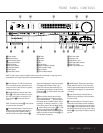
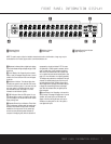
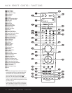
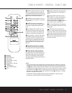
To assist you in making the correct connections for
multichannel input, output and speaker connections,
all connection jacks and terminals have been color-
coded in conformance with the CEA standards
as follows:
Front Left: White
Front Right: Red
Center: Green
Surround Left: Blue
Surround Right: Gray
Surround Back Left: Brown
Surround Back Right: Tan
Subwoofer: Purple
Digital Audio: Orange
Composite Video: Yellow
Component Video “Y”: Green
Component Video “Pr”: Red
Component Video “Pb”: Blue
NOTE: To make it easier to follow the installation instructions that refer to this illustration, a larger copy may be
downloaded from the Product Support section at www.harmankardon.com.