


REAR PANEL CONNECTIONS 9
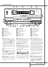
Rear Panel Connections
A
Preamp Outputs:When the jumper pins
that link the Amplifier Inputs
5
with these
outputs are removed, these jacks may be con-
nected to an external power amplifier.
B
Video Monitor Outputs: Connect this jack
to the composite and/or S-Video input of a TV
monitor or video projector to view the on-screen
menus and the output of any standard Video or
S-Video source selected by the receiver’s video
switcher.
C
Surround Back Preamp Outputs:When
the AVR is used in the 6.1 or 7.1 configuration,
connect these jacks to an optional, external
power amplifier to power the Surround Back
Channels.
D
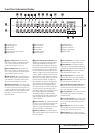
Front Speaker Outputs: Connect these
outputs to the matching + or – terminals on
your left and right speakers. In conformance with
the new CEA color code specification, the White
terminal is the positive, or ”+” terminal that
should be connected to the red (+) terminal on
Front Left speaker with the older color coding,
while the Red terminal is the positive, or ”+”
terminal that should be connected to the red (+)
terminal on Front Right speaker.Connect the
black (–) terminals on the AVR to the black (–)
terminals on the speakers. See page 15 for more
information on speaker polarity.
E
Center Speaker Outputs: Connect these
outputs to the matching + and – terminals on
your center channel speaker. In conformance
with the new CEA color code specification, the
Green Terminal is the positive,or ”+” terminal
that should be connected to the red (+) terminal
on speakers with the older color coding. Connect
the black (–) terminal on the AVR to the black
negative (–) terminal on your speaker. (See page
15 for more information on speaker polarity.)
F
Surround Speaker Outputs: Connect
these outputs to the matching + and – terminals
on your surround channel speakers. In confor-
mance with the new CEA color code specifica-
tion, the Blue terminal is the positive, or ”+” ter-
minal that should be connected to the red (+)
terminal on the Surround Left speaker with older
color coding, while the Gray terminal should be
connected to the red (+) terminal on the
Surround Right speaker with the older color cod-
ing. Connect the black (–) terminal on the AVR
to the matching black negative (–) terminals for
each surround speaker. (See page 15 for more
information on speaker polarity.)
G
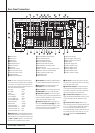
Switched AC Accessory Outlet:This out-
let may be used to power any device that you
wish to have turn on when the AVR is turned on
with the System Power Control switch
2
.
H
Unswitched AC Accessory Outlet:This
outlet may be used to power any AC device.The
power will remain on at this outlet regardless of
whether the AVR is on or off (in Standby), pro-
vided that the Main Power switch
1
is on.
Note: The total power consumption of all
devices connected to the accessory outlets
should not exceed 100 watts from the
Unswitched Outlet
H
and 50 W from the
Switched Outlet
G
.
I
AC Power Cord: Connect the AC plug to an
unswitched AC wall output.
J
Video 1/Video 2 Component Video
Inputs: Connect the Y/Pr/Pb component video
outputs of an HDTV Set-top convertor,satellite
receiver,or other video source device with com-
ponent video outputs to these jacks.
K
Monitor Component Video Outputs:
Connect these outputs to the component video
inputs of a video projector or monitor.When a
source connected to one of the Component
Video Inputs
JL
is selected the signal will
be sent to these jacks.
L
DVD Component Video Inputs: Connect
the Y/Pr/Pb component video outputs of a DVD
player to these jacks.
Note: All component inputs/outputs can be
used for RGB signals too, in the same way as
described for the Y/Pr/Pb signals,then connected
to the jacks with the corresponding color.
RGB connection is not possible if the source out-
puts a separate sync signal (see page 16).
M
Remote IR Output:This connection permits
the IR sensor in the receiver to serve other
remote controlled devices. Connect this jack to
the “IR IN” jack on Harman Kardon or other
compatible equipment.
N
Remote IR Input: If the AVR’s front-panel
IR sensor is blocked due to cabinet doors or
other obstructions, an external IR sensor may
be used. Connect the output of the sensor to
this jack.
O
Multiroom IR Input:Connect the output of
an IR sensor in a remote room to this jack to
operate the AVR’s multiroom control system.
P
Coaxial Digital Audio Output: Connect
this jack to the coaxial digital input connector on
a CD-R/RW,MiniDisc or other digital recorder.
Q
Optical Digital Audio Output: Connect
this jack to the optical digital input connector on
a CD-R/RW,MiniDisc or other digital recorder.
R
DVD Inputs: Connect the analog left/right
audio and composite or S-Video output of a
DVD player or other video source to these jacks.
S
Amplifier Trigger Jack: Connect this jack
to the compatible input trigger jack on a power
amplifier or other relay controlled device.The
connected product will turn on when the AVR is
turned on.
T
Video 1/Video 2 Inputs: Connect these
jacks to the PLAY/OUT composite or S-Video
jacks on a VCR or other video source.
U
Optical Digital Inputs: Connect the opti-
cal digital output from a DVD player,HDTV
receiver,the S/PDIF output of a compatible com-
puter sound card playing MP3 files or streams,
LD player,MD player or CD player to these jacks.
The signal may be either a Dolby Digital signal, a
DTS signal, a 2 channel MPEG 1 signal, an MP3
or HDCD data stream or a standard PCM digital
source.
V
Coaxial Digital Inputs: Connect the coax
digital output from a DVD player,HDTV receiver,
the S/PDIF output of a compatible computer
sound card playing MP3 files or streams, LD
player,MD player or CD player to these jacks.
The signal may be either a Dolby Digital signal,
DTS signal, a 2 channel MPEG 1 signal, an MP3
or HDCD data stream or a standard PCM digital
source. Do not connect the RF digital output of
an LD player to these jacks.
W
Video 3/Video 4 Inputs: Connect the
left/right audio and composite or S Video out-
puts of a video source such as a VCR, satellite
receiver,hard drive video recorder or other
device to these jacks.
X
Video 1/Video 2 Outputs: Connect the
left/right audio and composite or S-Video
Record/Input jacks on a VCR or camcorder to
these jacks.
Note: Either the Video or S-Video output of any
S-Video source must be connected to the
AVR, not both in parallel, otherwise the video
may be disturbed or its performance be adverse-
ly effected.