


18 INSTALLATION AND CONNECTIONS
System and Power Connections
The AVR 8500 is designed for flexible use with
multiroom systems, external control components
and power amplifiers.
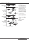
Main Room Remote Control Extension
If the receiver is placed behind a solid or smoked
glass cabinet door,the obstruction may prevent
the remote sensor from receiving commands. In
this event, the remote sensor of any Harman
Kardon or other compatible device, not covered
by the door,or an optional remote sensor may
be used. Connect the Remote IR Output of
that device or the output of the remote sensor to
the Remote IR Input jack
N
.
If other components are also prevented from
receiving remote commands, only one sensor is
needed. Simply use this unit’s sensor or a remote
eye by running a connection from the Remote
IR Output jack
M
to the Remote IR Input
jack on Harman Kardon or other compatible
equipment.
Multiroom IR Link
The key to remote room operation is to link the
remote room to the AVR 8500’s location with
wire for an infrared receiver,Video signals and
speakers or an amplifier.The remote room IR
receiver (this can be an optional IR receiver or
any other remotable Harman Kardon device in
the remote room with IR sensor integrated)
should be connected to the AVR via standard
coaxial cable. Connect the Remote IR Output
of the device or of the optional sensor with the
Multiroom IR Input jack
O
on the AVR’s rear
panel.
If other Harman Kardon compatible source
equipment is part of the main room installation,
the Remote IR Output jack
M
on the rear
panel should be connected to the IR IN jack on
that source device.This will enable the remote
room location to control source equipment func-
tions.
NOTE: All remotely controlled components must
be linked together in a “daisy chain”. Connect
the IR OUT jack of one unit to the IR IN of the
next to establish this chain.
Amplifier Trigger Connections
If an optional, external audio power amplifier is
used, this jack will provide the connection
needed to automate the amplifier's turn-on.
Connect this jack to the Trigger Input on a
compatible amplifer.When this connection is
made, the amplifier or any other trigger
controlled device such as a projection screen or
automatic blinds will be tuned on when the
AVR is on, and off when the AVR is off.
NOTE:When connecting any device to this jack,
make certain that proper connection polarity is
maintained and that the total current draw of
any device connected does not exceed 500
milliamps. If you are not familiar with this type
of connection, we recommend that you consult
your dealer or installer for more information.
Multiroom Connections
The AVR is equipped with complete multi-zone
capabilities that allow it to send a separate
audio/video source to the remote zone from the
one selected for use in the main room.
To view the video output of the source selected
for multizone operation at the remote location,
connect the wires connecting to the remote
video monitor to the Multizone output
jacks
7
.
Depending on the distance from the AVR to
the remote room, two options are available for
audio connection:
Option 1: Use high-quality, shielded audio
interconnect phono cable from the AVR’s loca-
tion to the remote room. In the remote room,
connect the interconnect cable to a stereo
power amplifier.The amplifier will be connected
to the room’s speakers.At the AVR, plug the
audio interconnect cables into the Multiroom
Output Jacks
7
on the AVR’s rear panel.
Option 2: Place the amplifier that will provide
power to the remote location speakers in the
same room as the AVR, and connect the
Multiroom Output jacks
7
on the rear panel
of the AVR to the audio input of the remote
room amplifier. Use the appropriate speaker wire
to connect the optional power amplifier to the
remote speakers. High-quality wire of at least
2.5 mm
2
is recommended for long multiroom
connections.
NOTE: In both options, you may connect an
optional IR sensor in the remote room to the
AVR via an appropriate cable.Connect the sen-
sor’s cable to the Multiroom IR Input
O
on
the AVR and use the Zone II remote to control
the room volume.Alternatively, you may install
an optional volume control between the output
of the amplifiers and the speakers.
External Audio Power Amplifier
Connections
If desired, the AVR may be connected to option-
al, external audio power amplifiers or used with
equalizers or speaker systems that require con-
nection between the preamp and amplifier sec-
tions of a receiver.
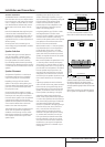
To make these connections, remove the jumpers
that connect the Preamp Out jacks
A
and
Amplifier In jacks
5
for the channels to be
used with external devices. Store the jumpers in
a safe place so that the AVR may be used in its
normal mode at a future date, if desired.
When an external amplifier is used, connect the
Preamp Out jacks
A
to the inputs on the
amplifier.When an equalizer or speaker proces-
sor is used, connect the Preamp Out jacks
A
to the inputs of the processor,and connect the
outputs of the processor back to the Amplifier
In jacks
5
on the AVR. Note that when external
amplifiers or devices are used, volume is still
controlled by the AVR, although additional vol-
ume controls on the external device may affect
volume and output levels from the AVR.
AC Power Outputs
This unit is equipped with two accessory AC out-
lets.They may be used to power accessory
devices, but they should not be used with high-
current draw equipment such as power ampli-
fiers.The total power draw to the Unswitched
Outlet
H
must not exceed 100 watts, that to
the Switched Outlet
G
50 watts.
The Switched
G
outlet will receive power only
when the unit is on completely.This is recom-
mended for devices that have no power switch
or a mechanical power switch that may be left in
the “ON” position.
NOTE: Many audio and video products go into a
Standby mode when they are used with
switched outlets, and cannot be fully turned on
using the outlet alone without a remote control
command.
The Unswitched
H
outlet will receive power
as long as the unit is plugged into a powered AC
outlet and the Main Power Switch
1
is on.
Installation and Connections