


16 INSTALLATION AND CONNECTIONS
Installation and Connections
SCART A/V Connections
For the connections described above your video
device needs RCA (cinch) connectors or/and S-
Video connectors for all Audio and Video signals:
Any normal video device (Not SVHS or High 8)
for only playback needs 3 RCA jacks, VCRs for
record and playback even 6 RCA jacks. Any
S-Video device (SVHS, High 8) needs 2 RCA
(Audio) and 1 S-Video jack (Video), if it´s a
playback unit, or 4 RCA (Audio In/Out) and
2 S-Video (Video In/Out) jacks, if it´s a recording
VCR.
Many european video devices are equipped with
RCA (Cinch) or S-Video jacks only partially, not
for all audio and video in/outputs needed as
described above, but with a so called Scart or
Euro-AV connector (almost rectangular jack with
21 pins, see drawings on next page).
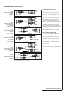
In that case the following Scart to Cinch
adapters or cables are needed:
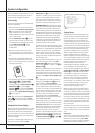
• Units for playback, such as satellite receivers,
camcorders, DVD or LD players, need an
adapter from Scart to 3 RCA plugs, see fig. 1
(normal video devices) or from Scart to 2
RCA+1 S-Video plugs, see fig. 4 (S-Video
devices).
• HiFi VCRs need an adapter from Scart to 6
RCA plugs, see fig. 2 (normal video), or from
Scart to 4 Audio+2S-Video jacks, see fig. 5
(S-Video VCR). Read carefully the instruction
attached to the adapter to find which of the
six plugs is used for the record signal to the
VCR (connect with the AVR´s Out jacks) and
for the playback signal from the VCR (connect
with the AVR´s In jacks). Do not misconnect
Audio and Video signals. Don´t hesitate to
consult your dealer, if you are uncertain.
• If you use only normal video devices the TV
monitor needs an adapter from 3 RCA plugs
to Scart (fig. 3) only. If also S-Video devices are
used an adapter from 2 RCA+1S-Video plugs
to Scart is needed additionally (fig. 6),
connected to the SCART input on your TV that
is provided for S-Video.
Note that only the video plugs (the "yellow"
cinch plug in fig. 3 and the S-Video plug in
fig. 6) must be connected to the TV Monitor
Output
B
, and the volume on the TV must be
reduced to minimum.
Important Note for Adapter Cables:
If the cinch connectors of the adapter you’ll use
are labeled, connect the Audio and Video ”In”
plugs with the corresponding Audio and Video
”In” jacks on the AVR (and with a VCR connect
the ”Out” plugs to the ”Out” jacks on the AVR).
Note that with some adapter types it may be
just turned around: If no signal is audible/ visible
when the VCR is playing connect the “Out”
plugs to the ”In” jacks on the AVR and turned
around. If the adapter plugs are not labeled in
that way, pay attention to the signal flow direc-
tions as shown in the diagrams above and in the
instruction attached to the adapter. If uncertain,
don’t hesitate to consult your dealer.
Important Notes for S-Video connections:
1. Only the S-Video In/Out of S-Video devices
must be connected to the AVR, NOT both,
normal video and S-Video In/Outputs (except the
TV, see item below).
When both connections are made, only the
S-Video signal will be viewed on the screen.
2. Like most common AV units the AVR does not
convert the Video signal to S-Video, only vice
versa.Thus both connections must be made from
the AVR to the TV if both, Video and S-Video
sources, are used, and the appropriate input on
the TV must be selected.
being the factory default. For information on
changing the input assignments for either the
component video jacks or the DVD player’s audio
connection, see page 20.
7. If you have other devices with Y/Pr/Pb or RGB
component video outputs, connect the source
device to the Component Video 2 Inputs
N
.
The audio connections may be to any of the
Video Audio Inputs
QSTÔ
or the Optical
or Coaxial Digital Inputs
UV*Ó
.When
using either of the Component Video Inputs,
make certain that the audio and video inputs are
properly configured in the
INPUTSETUP
menu, as described on page 20.
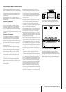
8. If the component video inputs are used,
connect the Component Video Output
K
to
the component video inputs of your TV, projector
or display device.
9. If you have a camcorder, video game or other
audio/video device that is connected to the AVR
on a temporary, rather than permanent basis,
connect the audio, video and digital audio out-
puts of that device to the Front Panel Inputs
*ÓÔ
.A device connected to the Video 4
jacks
Ô
is selected as the Video 4 input, and
connected to the digital jacks
*Ó
it is selected
as "Optical 3" or "Coaxial 3" input. (See page
20 for more information on input configuration.)
Video Connection Notes:
• Y/Pr/Pb Component, RGB (see page 17),
or Composite video signals may only be viewed
in their native formats and will not be convert-
ed to the other formats. S-Video signals will be
converted to composite signal.The OSD can be
viewed on the TV screen in any case, with Video
or S-Video input selected on the TV.
• When the component video jacks are used, the
on-screen menus will not be visible. You must
switch to the standard composite or S-Video
input on your TV to view those menus.
• All component inputs/outputs can be used for
RGB signals too, in the same way as described
for the Y/Pr/Pb signals, then connected to the
jacks with the corresponding color.
But this is only correct as long as only the three
RGB video signals are output by the video
source, with a sync signal in the "G" signal
only, without any sync signal output separately
by the source.