


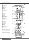

18 INSTALLATION AND CONNECTIONS
System and Power Connections
The AVR 430 is designed for flexible use with
multiroom systems, external control components
and power amplifiers.
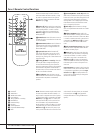
Main Room Remote Control Extension
If the receiver is placed behind a solid or smoked
glass cabinet door, the obstruction may prevent
the remote sensor from receiving commands. In
this event, the remote sensor of any Harman
Kardon or other compatible device, not covered
by the door, or an optional remote sensor may
be used. Connect the Remote IR Output of
that device or the output of the remote sensor to
the Remote IR Input jack
N
.
If other components are also prevented from
receiving remote commands, only one sensor is
needed. Simply use this unit’s sensor or a remote
eye by running a connection from the Remote
IR Output jack
M
to the Remote IR Input
jack on Harman Kardon or other compatible
equipment.
Multiroom IR Link
The key to remote room operation is to link the
remote room to the AVR’s location with wire for
an infrared receiver and speakers or an amplifier.
The remote room IR receiver (this can be an
optional IR receiver or any other remotable
Harman Kardon device in the remote room with
IR sensor integrated) should be connected to the
AVR via standard coaxial cable. Connect the
Remote IR Output of the device or of the
optional sensor with the Multiroom IR Input
jack
O
on the AVR’s rear panel.
If other Harman Kardon compatible source
equipment is part of the main room installation,
the Remote IR Output jack
M
on the rear
panel should be connected to the IR IN jack on
that source device. This will enable the remote
room location to control source equipment
functions.
NOTE: All remotely controlled components must
be linked together in a “daisy chain”. Connect
the IR OUT jack of one unit to the IR IN of the
next to establish this chain.
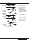
Multiroom Audio Connections
Depending on your system`s requirement and
distance from the AVR to the remote room, three
options are available for audio connection:
Option 1: Use high-quality, shielded audio
interconnect phono cable from the AVR’s loca-
tion to the remote room. In the remote room,
connect the interconnect cable to a stereo
power amplifier.The amplifier will be connected
to the room’s speakers.At the AVR, plug the
audio interconnect cables into the Multiroom
Output Jacks
7
on the AVR’s rear panel.
Option 2: Place the amplifier that will provide
power to the remote location speakers in the
same room as the AVR, and connect the
Multiroom Output jacks
7
on the rear panel
of the AVR to the audio input of the remote
room amplifier. Use the appropriate speaker wire
to connect the optional power amplifier to the
remote speakers. High-quality wire of at least
2.5 mm
2
is recommended for long multiroom
connections.
Option 3: Taking advantage of the AVR’s built-
in seven-channel amplifier, it is possible to use
two of the amplifier channels to power speakers
in the remote room.When using this option you
will not be able to use the full 7.1-channel
capabilities of the AVR in the main listening
room, but you will be able to add another
listening room without additional external
power amplifiers. To use the internal amplifiers
to power a remote zone, connect the speakers
for the remote room location to the Surround
Back/Multiroom Speaker Outputs
c
.
Before using the remote room you will need to
configure the amplifiers for surround operation
by changing a setting in the Advanced Select
menu, following the instructions shown on page
37.
NOTE: For all options, you may connect an
optional IR sensor (Harman Kardon He1000) in
the remote room to the AVR via an appropriate
cable. Connect the sensor’s cable to the
Multiroom IR Input
O
on the AVR and use
the Zone II remote to control the room volume.
Alternatively, you may install an optional volume
control between the output of the amplifiers and
the speakers.
A-BUS Installation Connections
The AVR is among the very few receivers
available today that offers built-in A-BUS Ready
®
operation.When used with an optional A-BUS
keypad or control module, you have all the
benefits of remote zone operation without the
need for an external power amplifier.
To use the AVR with an approved A-BUS
product, simply connect the keypad or module
that is in the remote room to the AVR using
standard “Category 5” wiring that is properly
rated for the inwall use specific to the installa-
tion.Terminate the wiring at the receiver end to
a standard RJ-45 jack in compliance with the
instructions furnished with the A-BUS module.
No further installation or adjustment is needed,
as the A-BUS connector on the AVR routes the
signals in and out of the keypad to their proper
destination for power, signal source and control.
The output fed to the A-BUS jack is determined
by the AVR’s multiroom system, and the menus
may be used as is.
RS-232 Connections
The AVR is equipped with an RS-232 Serial
Connection Port
d
that may be used for two
purposes. When the port is connected to a com-
patible, optional, external computer, keypad or
control system the AVR is capable of bi-direc-
tional communications that enable the external
system to control the AVR, and for the AVR to
report status and handshake data back to the
controller. Use of the RS-232 port for this type of
control requires specific technical knowledge,
and we recommend that any connection and
programming for control be made by a trained
installer or technician familiar with the equip-
ment being used.The RS-232 port may also be
used as an access point through which the AVR’s
operating system and surround mode memories
may be updated via connection to a compatible
computer.At the time that any upgrade is avail-
able, instructions for making the connection and
installing the upgrade will be available through
the Product Support area of the Harman Kardon
Web site at www.harmankardon.com.
The physical connection to the AVR’s RS-232
port is a standard D-9 connection but to assure
compatible and proper operation, specific soft-
ware commands and pin wiring schemes may be
required.
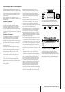
AC Power Connections
This unit is equipped with two accessory AC
outlets. They may be used to power accessory
devices, but they should not be used with
high-current draw equipment such as power
amplifiers. The total power draw to the
Unswitched Outlet
H
must not exceed
100 watts, that to the Switched Outlet
G
50 watts.
The Switched
G
outlet will receive power only
when the unit is on completely. This is recom-
mended for devices that have no power switch
or a mechanical power switch that may be left in
the “ON” position.
NOTE: Many audio and video products go into a
Standby mode when they are used with
switched outlets, and cannot be fully turned on
using the outlet alone without a remote control
command.
The Unswitched
H
outlet will receive power
as long as the unit is plugged into a powered AC
outlet and the Main Power Switch
1
is on.
The AVR features a removable power cord that
allows wires to be run to a complex installation
so that the unit, itself, need not be installed until
it is ready for connection.When all connections
described above have been made, connect the
AC Power cord to the AC Power Cord Jack
I
.
Installation and Connections