


INSTALLATION AND CONNECTIONS 15
INSTALLATION AND CONNECTIONS
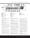
should be connected to the Video 1 Out Jacks
bk on the AVR 125.
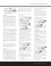
2. Connect the analog audio and video outputs of a
television set or any other video source to the
Video 2
Jacks
d .
3. Connect the analog audio and video outputs of a
cable TV converter or satellite receiver, or any other
video source, to the
Video 3 Jacks %^ on the
front panel of the AVR 125.
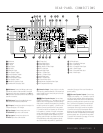
4. Connect the analog audio and video outputs of
a DVD or laser disc player to the
DVD Jacks
°gh. When a digital audio connection is used
for your DVD player, the default connection is the
Coaxial Digital Input 1 Jack ·. However, the
connection may also be made to any of the
Optical
c# or Coaxial ·$ Digital Inputs, provided
that the digital input source selection is changed as
shown on page 23. If your DVD or DVD-Audio player
includes an onboard surround decoder and 6-channel
line-level audio outputs, you may connect these audio
outputs to the
6-Channel Direct Inputs e. When
you wish to hear this decoded audio, select the DVD
Input first in order to select the video signal from the
DVD player, then select the 6-Channel Direct Input
source for the audio.
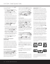
5. Connect the digital audio outputs of a DVD player,
satellite receiver, cable box or HDTV converter to the
appropriate
Optical or Coaxial Digital Inputs
·c#$.
6. Connect the
Video Monitor Output ‡f jacks
on the receiver to the composite or S-Video input of
your television monitor or video projector.
VIDEO CONNECTION NOTE:
• Composite and S-Video signals may only be viewed
in their native formats. The AVR 125 will not convert
signals from composite to S-Video, or vice versa.
S-Video inputs may only be viewed when the
AVR 125 is connected to a TV set or video display
with S-Video capability. If you use both standard
composite video and S-Video sources in your
system, it is important that you connect both an
S-Video cable and a standard composite video
cable (a coax cable with an RCA plug on both
ends) between the AVR 125 and your TV or projec-
tor. When it is necessary to make both types of
connections to your TV set, use different inputs if
possible. Consult the instructions for your TV set or
projector for more information on connecting both
types of signals.
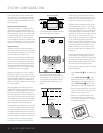
Power Connections
This unit is equipped with two accessory AC outlets.
They may be used to power accessory devices, but
they should not be used with high-current draw equip-
ment such as power amplifiers. The total power draw
to each outlet may not exceed 100 watts.
The
Switched AC Accessory Outlet ¤ will receive
power only when the unit is on. This is recommended
for devices that have no power switch or a mechanical
power switch that may be left in the “ON” position.
NOTE: Many audio and video products go into a
Standby mode when they are used with switched out-
lets, and cannot be fully turned on using the outlet
alone without a remote control command.
The
Unswitched AC Accessory Outlet ‹ will
receive power as long as the unit is plugged into a
powered AC outlet.
Finally, when all connections are complete, plug the
Power Cord › into a nonswitched 120-volt AC wall
outlet. You’re almost ready to enjoy the AVR 125!
33
32
31