


REAR-PANEL CONNECTIONS 9
REAR-PANEL CONNECTIONS
›
fi
fl
°
‡
¢
•
‚
¡
™
£
∞
¶
⁄
¤
‹
b
c
d
e
f
g
j
k
h
i
·
a
ª
§
31
33
32
SURR SURR
, 1A
, 0.5A
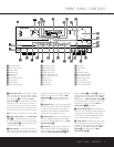
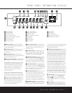
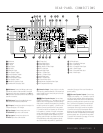
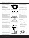
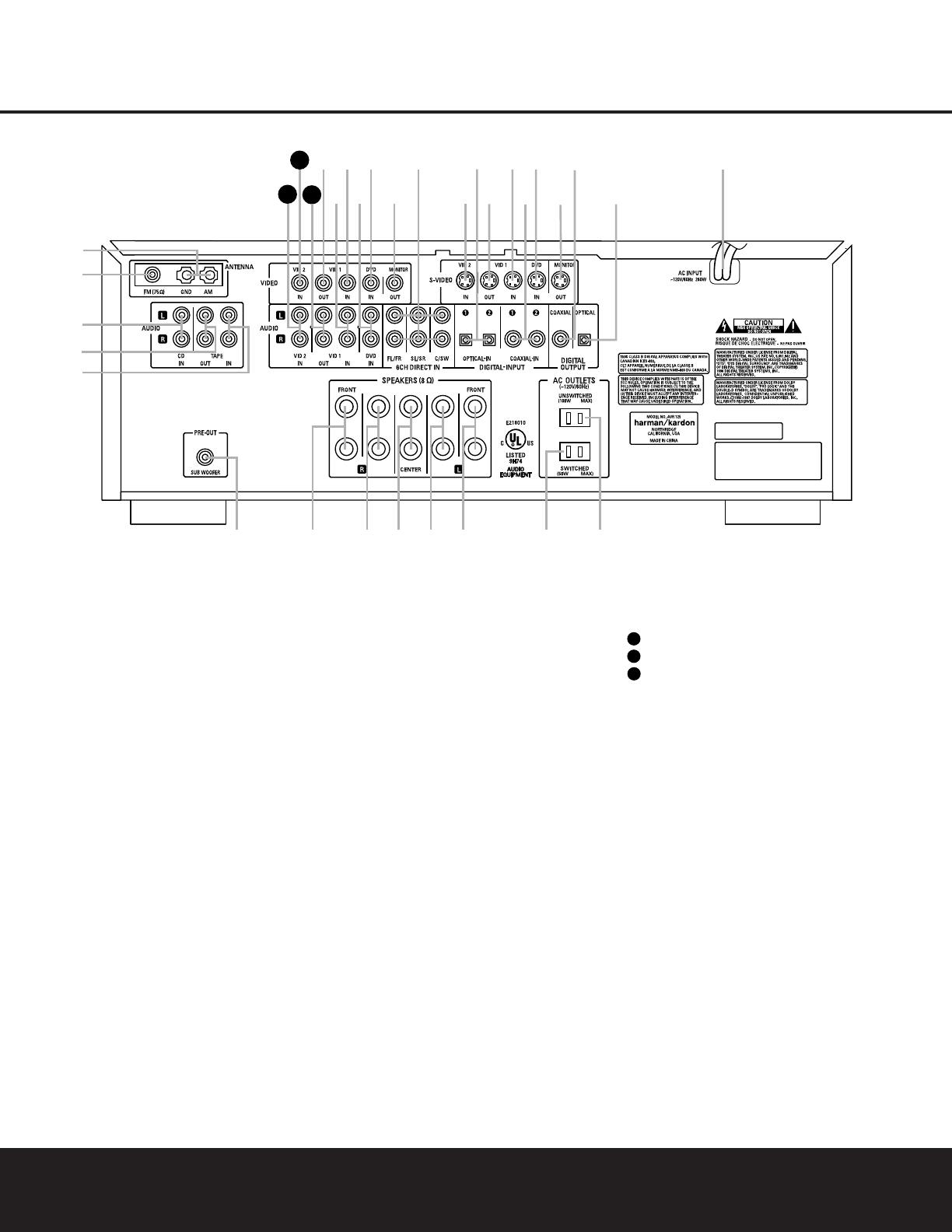
¡ AM Antenna
™ FM Antenna
£ CD Inputs
¢ Tape Outputs
∞ Tape Inputs
§ Subwoofer Output
¶ Front Speaker Outputs
• Surround Speaker Outputs
ª Front Speaker Outputs
‚ Surround Speaker Outputs
⁄ Front Speaker Outputs
¤ Switched AC Accessory Outlet
‹ Unswitched AC Accessory Outlet
› AC Power Cord
fi Optical Digital Output
fl Coaxial Digital Output
‡ Video Monitor S-Video Output
° DVD S-Video Input
· Coaxial Digital Inputs
a Video 1 S-Video Input
b Video 1 S-Video Output
c Optical Digital Inputs
d Video 2 S-Video Input
e 6-Channel Direct Inputs
f Video Monitor Composite Video Output
g DVD Composite Video Input
h DVD Audio Inputs
i Video 1 Composite Video Input
j Video 1 Audio Inputs
k Video 1 Composite Video Output
Video 1 Audio Outputs
Video 2 Composite Video Input
Video 2 Audio Inputs
33
32
31
¡ AM Antenna: Connect theAM loop antenna sup-
plied with the receiver to these terminals. If an external
AM antenna is used, make connections to the
AM and
GND terminals in accordance with the instructions sup-
plied with the antenna.
™ FM Antenna: Connect the supplied indoor or an
optional external FM antenna to this terminal.
£ CD Inputs: Connect these jacks to the output of a
compact disc player or CD changer.
¢ Tape Outputs: Connect these jacks to the
RECORD/INPUT jacks of an audio recorder.
∞ Tape Inputs: Connect these jacks to the
PLAY/OUT jacks of an audio recorder.
§ Subwoofer Output: Connect this jack to the line-
level input of a powered subwoofer. If an external sub-
woofer amplifier is used, connect this jack to the sub-
woofer amplifier input.
¶ª⁄ Front Speaker Outputs: Connect these
outputs to the matching + or – terminals on your front
speakers. When making speaker connections, always
make certain to maintain correct polarity by connecting
the black terminal to the negative (–) terminal on the
speakers. Connect the white terminal to the positive
(+) terminal on the left front speaker, the red terminal
to the positive (+) terminal on the right front speaker
and the green terminal to the positive (+) terminal on
the center front speaker. Newer speakers may have
matching color terminals in accordance with the new
CEA specifications, while existing speakers typically
use a red terminal for the positive (+) speaker wire
connection. (See page 14 for more information on
speaker polarity.)
•‚ Surround Speaker Outputs: Connect these
outputs to the matching + or – terminals on your left
and right surround speakers. When making speaker
connections always make certain to maintain correct
polarity by connecting the black terminal to the nega-
tive (–) terminal on the speakers. Connect the blue
terminal to the positive (+) terminal on the left sur-
round speaker and the gray terminal to the positive
(+) terminal on the right surround speaker. Newer
speakers may have matching color terminals in accor-
dance with the new CEA specifications, while existing
speakers typically use a red terminal for the positive
(+) speaker wire connection. (See page 14 for more
information on speaker polarity.)