


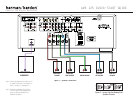
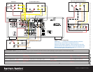
SPEAKER AND VIDEO CONNECTIONS
SURR SURR
, 1A
, 0.5A
CD PLAYERAM AntennaFM Antenna
AUDIO RECORDER
L R Optical Coax
L R Optical Coax
REC/IN
PLAY/OUT
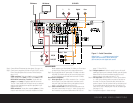
Step 4. Connect AM and FM antennas (as shown above). (See page 14.)
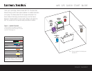
Step 5. Connect source components, as shown in Figures 4 and 5, and the
Device Connection Options chart on the back of this Guide (see
pages 14–15).
AUDIO connections: Right channel (red) on source to right (red)
on AVR, and left channel (
white) on source to left (white) on AVR.
DIGITAL AUDIO connections, if available: Choose either coax
(
orange) to coax (orange) OR optical to optical for each device.
The Coax 1 input defaults to the DVD player, but may be reassigned.
Assign the other digital inputs and outputs as appropriate for your
equipment (see Step 7).
VIDEO connections: Choose either composite (yellow) or S-Video
(4-pin) for each video source. Connect the composite and S-Video
Monitor outputs to your Video Monitor (TV). Switch your TV set’s input
to match the type of video used for the currently selected source.
Step 6. Plug all components into AC power outlets. The outlets on the back
of the AVR 125 should be used
only for low-current products, such
as CD or DVD players, and the total should not exceed 100 watts.
Basic Receiver Configuration
Step 7. Select digital inputs: If your DVD is connected to Coax 1, no adjust-
ment is needed. For any other digital-device connections, use the
front-panel Digital Select button and the arrow buttons to select an
optical or coax digital input (see pages 20 and 23).
Step 8.
Select a surround mode: Press the Surround Mode button on the
front panel to select Dolby
®
Pro Logic
®
II – Movie. (You may select
other modes later as you become familiar with the AVR 125; see
pages 17, 20 and 22–23.)
Step 9.
Configure speakers: No action is needed if you have five “small”
satellite-type speakers and a subwoofer. Otherwise, press the Speaker
button and then the Set and arrow buttons to select the correct
speaker choices for your system (see pages 17–18).
Step 10.
Set output levels: Set the Balance to 12 o’clock, and the Volume
to –15dB. Sit in the listening position and press the Test button on
the remote. The Test tone (it sounds like static) will circulate from
speaker to speaker. Press the up/down arrow keys to adjust the level
of each speaker until they all sound the same. If you have an SPL
meter, set it to 75dB, C-Weighting Slow. Press the Test button again.
(See pages 18–19).
Step 11.
Your system is configured – sit back and enjoy!
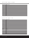
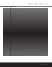
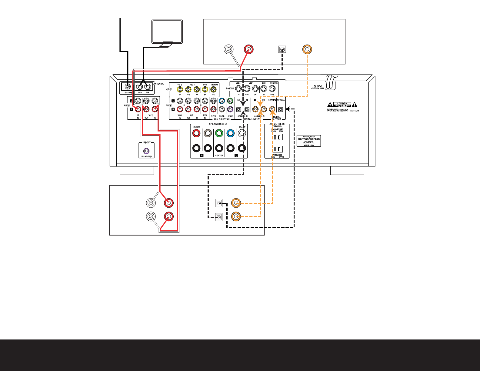
Figure 4 – Audio Connections
Dashed lines (––––) indicate coax and optical
digital audio connections. Choose either type
(but not both) for each digital audio source.