


6 FRONT-PANEL CONTROLS
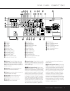
FRONT-PANEL CONTROLS
In Manual tuning mode, tap the button lightly and note
that the tuner will step up one frequency increment per
button press. When the button is held for a few sec-
onds you will note that the unit will quickly advance
through the frequency band. Release it and the tuner
will stop. In Auto tuning mode, each press of the but-
ton will search for the next station with an acceptable
signal. Press and hold the button to skip through the
acceptable stations. When the button is released, the
tuner will not stop until it reaches a station with an
acceptable frequency.
To switch back and forth between the Auto and
Manual tuning modes, press the
Tuning Mode
Selector
@.
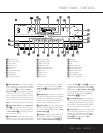
9 AM/FM Selector: Pressing this button will auto-
matically switch the AVR 125 to the Tuner mode.
Pressing it again will switch between the AM and FM
frequency bands. (See page 25 for more information
on the tuner.)
) Preset Stations Selector: Press this button to
scroll up or down through the list of stations that have
been entered into the preset memory. (See page 25
for more information on tuner presets.)
! Input Source Selector: Press this button to
change the input by scrolling up or down through the
list of
Input Indicators .
@ Tuning Mode Selector: Press this button to select
Auto or Manual tuning. When the button is pressed so
that the
AUTO Indicator R lights, the tuner will search
for the next station with an acceptable signal when the
Tuning Selector 8u is pressed. When the button
is pressed so that the
AUTO Indicator R is not lit,
each press of the
Tuning Selector 8u will
increase the frequency.This button may also be used to
switch between Stereo and Mono modes for FM radio
reception.When weak reception is encountered, press
the button until the
STEREO Indicator P goes out to
switch to Mono reception. Press and hold again to
switch back to STEREO mode. (See page 25 for more
information on using the tuner.)
# Digital Optical 3 Input: Connect the optical digital
audio output of an audio or video product to this jack.
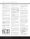
When the input is not in use, be certain to keep the
plastic cap installed to avoid dust contamination that
might degrade future performance.
$ Digital Coax 3 Input: This jack is used for con-
nection to the output of portable audio devices, video
game consoles or other products that have a coax
digital audio jack.
% Video 3 Video Input Jacks: These jacks may be
used for temporary connection to the composite or S-
Video output of video games, camcorders or other
portable video products.
^ Video 3 Audio Input Jacks: These audio jacks
may be used for temporary connection to video
games or portable audio/video products such as cam-
corders and portable audio players.
& Bass Control: Turn this control to modify the low-
frequency output of the left/right channels by as much as
±10dB, when the unit is in the “Surround Off” mode. Set
this control to a suitable position for your taste or room
acoustics.
* Balance Control: Turn this control to change the
relative volume for the front left/right channels.
NOTE: For proper operation of the surround modes
this control should be at the midpoint or “12 o’clock”
position.
( Treble Control: Turn this control to modify the high
frequency output of the left/right channels by as much as
±10dB, when the unit is in the “Surround Off” mode. Set
this control to a suitable position for your taste or room
acoustics.
Ó Volume Control: Turn this knob clockwise to
increase the volume, counterclockwise to decrease the
volume. If the AVR 125 is muted, adjusting the
Volume Control Ó will automatically release
the unit from the silenced condition.
Ô Set Button: When making choices during the
setup and configuration process, press this button
to enter the desired setting as shown in the
Main
Information Display
Û into the AVR 125’s memory.
The set button may also be used to change the display
brightness. (See page 26.)
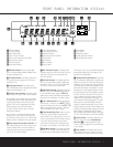
Input Indicators: A green LED will light in front of
the input that is currently being used as the source for
the AVR 125.
Ò Delay: Press this button to begin the sequence
of steps required to enter delay time settings. (See
page 19 for more information on delay times.)
Ú Digital Input Selector: When playing a source
that has a digital output, press this button to select
between the
Optical #c and Coaxial $·
Digital inputs or to select the source’s analog input.
(See pages 23–25 for more information on digital
audio.)
Û Main Information Display: This display delivers
messages and status indications to help you operate
the receiver. (See pages 7–8 for a complete explana-
tion of the Information Display.)
Ù Channel Select Button: Press this button to
begin the process of trimming the channel output lev-
els using an external audio source. (For more informa-
tion on output level trim adjustment, see page 25.)
ı Speaker Select Button: Press this button to
begin the process of configuring the unit to match the
type of speakers used in your listening room. (See
pages 16–19 for more information on speaker setup
and configuration.)
ˆ Test Tone Selector: Press this button to begin
the process of adjusting the channel output levels
using the internal test tone as a reference. (For more
information on output level adjustment, see page 18.)
˜ Surround Mode Indicators: A green LED will
light in front of the surround mode that is currently
in use.
¯ Remote Sensor Window: The sensor behind
this window receives infrared signals from the remote
control. Aim the remote at this area and do not block
or cover it.
33