


10 REAR-PANEL CONNECTIONS
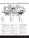
REAR-PANEL CONNECTIONS
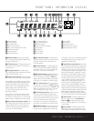
¤ Switched AC Accessory Outlet: This outlet may
be used to power any device you wish to have turned
on or off at the same time as the AVR 125.Any device
connected to this outlet will be off when the AVR 125
is in the Standby mode, and power will be supplied to
the outlet when the AVR 125 is turned on.
‹ Unswitched AC Accessory Outlet: This outlet
may be used to power any AC device. The power will
remain on at this outlet regardless of whether the
AVR 125 is on or off.
IMPORTANT NOTE: The total power consumption of
all devices connected to the accessory outlets should
not exceed 100 watts. Do not connect power amplifiers
or other high-current draw devices to these outlets.
› AC Power Cord: Connect the AC plug to an
unswitched AC wall outlet.
fi Optical Digital Output: Connect this jack to the
matching digital audio input connector on a digital
recorder such as a CD-R or MiniDisc recorder.
fl Coaxial Digital Output: Connect this jack to the
matching digital audio input connector on a digital
recorder such as a CD-R or MiniDisc recorder.
‡f Video Monitor Outputs: Connect these jacks
to the composite or S-Video input of a TV monitor or
video projector to view the output of any standard
video source selected by the receiver’s video switcher.
°g DVD Video Inputs: Connect one of these
jacks to the composite or S-Video output jacks on a
DVD or other video source.
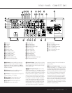
· Coaxial Digital Inputs: Connect the coax digital
audio output from a DVD player, HDTV receiver, LD
player, satellite receiver, cable box, MiniDisc recorder or
CD player to these jacks.The signal may be either a
Dolby Digital signal, DTS signal or a standard PCM digital
source. Do not connect the RF digital output of an
LD player to these jacks.
ai Video 1 Video Inputs: Connect one of these
jacks to the
PLAY/OUT composite or S-Video jacks
on a VCR or other video source.
bk Video 1 Video Outputs: Connect one of these
jacks to the
RECORD/INPUT composite or S-Video
jack on a VCR.
c Optical Digital Inputs: Connect the optical digital
audio output from a DVD player, HDTV receiver, LD
player, satellite receiver, cable box, MiniDisc player or
recorder, or CD player to these jacks.The signal may
be either a Dolby Digital signal, a DTS signal or a
standard PCM digital source.
d Video 2 Video Inputs: Connect one of these
jacks to the
PLAY/OUT composite or S-Video jacks
on a TV, VCR or other video source.
e 6-Channel Direct Inputs: If an external digital
audio decoder is used, connect the outputs of that
decoder to these jacks.
These jacks have been color-coded as follows to
assist you in making correct channel connections:
Front Left White
Front Right Red
Center Green
Surround Left Blue
Surround Right Gray
Subwoofer Purple
h DVD Audio Inputs: Connect these jacks to the
analog audio jacks on a DVD player or other source
device.
NOTE: The default setting for the audio input associated
with DVD is the Coaxial Digital Input 1 ·. If you
connect the audio outputs of a DVD player to the ana-
log jacks
h, change the input setting as shown on
page 20.
j Video 1 Audio Inputs: Connect these jacks to
the
PLAY/OUT audio jacks on a VCR or other video
source.
Video 1 Audio Outputs: Connect these jacks to
the
RECORD/INPUT audio jacks on a VCR.
Video 2 Audio Inputs: Connect these jacks to
the
PLAY/OUT audio jacks on a VCR, satellite receiver,
cable box, video game or other composite video
source.
33
31
32