


I NTRODUCTION
– 1 –
The Hafler P7000 is a two channel professional power amplifier suitable for use in any sound reinforcement
situation where faithful, accurate reproduction is required. The amplifier uses forced air fan cooling to deliver
high power output in a compact size. Status indicators on the front panel give a visual representation of
amplifier and system operation. Input configuration switching and active crossovers enhance the flexibility
when used in multiple amp systems, without requiring the use of additional equipment. The use of our
patented trans•nova circuit topology and MOSFET output stage ensures reliable, long term operation which
is backed by our five year warranty.
This manual contains information on using the P7000 amplifiers. It is organized into three main sections.
“Installation” covers the location and connection of the amplifier in the system. Like many precision
components, careful attention to the initial setup can yield dividends in higher performance and trouble-free
use. “Operation” covers the controls and features of the amplifiers and how to use them to get the best effect.
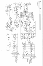
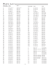
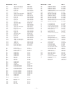
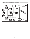
The “Technical Reference” section contains field service information; in addition to the schematic and parts
list there are block diagrams and circuit operation explanations useful for technicians. We strongly urge
reading over the Installation and Operation portions of this manual before putting the amplifier into service.
The circuitry used in the Hafler Professional power amplifiers is our trans•nova (TRANSconductance NOdal
Voltage Amplifier, US Patent 4,467,288) circuit. The P7000 also utilizes our proprietary DIABLO (Dynamically
Invariant AB Linear Operation, patent application in progress) transconductance driver stage which combines
the linearity of Class A operation with the current headroom of a Class B system. When combined with the
robust output stage used in the P7000, DIABLO yields lower high frequency distortion without the sonic
penalties associated with increasing the negative feedback. We have been using MOSFETs in our power
amplifiers since the 1970s. During this time, they proved to be extremely fault tolerant, even in abusive
situations. This ruggedness enables the amplifier to drive reactive speaker loads without the performance and
sound penalties imposed by elaborate Safe Operating Area protection schemes.
Active crossovers are incorporated at the input of the amplifier. These crossovers are controlled through the
use of our XCard plug-in modules. Each XCard can operate as a full-range, high-pass or low-pass filter with a
12dB per octave Butterworth alignment. Each channel utilizes two XCards which in combination can be
configured as a 24dB per octave slope or a 12dB per octave bandpass filter. Since the XCard contains the resistors
and capacitors that establish the crossover Q and frequency; specific system requirements can easily be
accommodated just by changing the component values.
Input configuration switches allow the amplifier to be configured for conventional stereo, two channel mono
or single channel bridged use. When the amplifier is run in two-channel mono mode, the level controls and
crossovers for each channel are fully functional which allows for using the amplifier as a single channel in a
bi-amped system.
Specialized circuits which prevent damage to the amplifiers and speakers have been carefully implemented to
avoid affecting the audio signal. A soft start circuit prevents sending potentially destructive turn-on and turn-
off transients to the speakers. A thermal sensing network monitors the heatsink temperature and shuts down
the amplifier to protect it from excessive operating heat. The need for internal fuses has been eliminated; a
sensing circuit monitors the output and shuts down the power when it detects a short in the output load.
Each channel of the amplifier has been built as a self-contained module. This modular arrangement simplifies
construction and improves service accessibility. The circuit board assembly makes extensive use of surface
mount components in the low power portion of the audio circuitry. Automated equipment is used to place and
solder the components which yields greater uniformity and reliability.
The front panel has controls for input level adjustment and the power switch. In addition, LED indicators give
a visual representation of the operating status of each channel. The THERMAL and SHORT indicators light to
show when these protection circuits have been activated. The clip indicator helps prevent damaging the
speakers by showing when the amplifier is overdriven. The SIGNAL indicator lights to show the presence of
an audio signal.