


– 16 –
AMPLIFIER MODULE REPLACEMENT
The amplifier modules have been designed to eliminate the need for a special workplace if a field exchange becomes
necessary. All wire connections are made with quick connect terminals so soldering is not necessary. The following
tools are needed to disassemble the amplifier:
Allen wrench, 9/64
Phillips screwdriver, #1 tip
Thin nose pliers
Small cutters
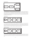
Remove the four Phillips head screws, located on the rear panel, which secure the input jacks. Remove the six 9/64
Allen screws that hold the cover. These are located along the top edge, two on each side and two on the rear. Lift the
cover from the rear and remove it. Remove the level control knob. The wire harnesses have been bundled for neatness.
Cut the ties to free the bundles.
Disconnect the red and black output wires from the binding posts and the fan and power wires from the amplifier drive
card. Disconnect the transformer secondary wires from the bridge rectifier and PC board. Unplug the gray mono cables.
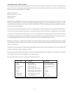
The heatsink is attached to the chassis by three screws, two outside and one inside. Remove the two 9/64 Allen screws
on the bottom edge of the side of the amplifier. Remove the Phillips screw located behind the level control, which is
accessible through the hole in the PC board. The module can now be lifted from the chassis.
Prepare a new Channel 1 module for installation by setting the input mode switches to the default position according
to the markings adjacent to the switches. Prepare a Channel 2 module by duplicating the switch settings of the module
which was removed.
Install the new module and check the position and alignment of the indicator LEDs. Replace the level control knob and
check the alignment while securing the module.
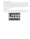
Plug in the gray mono cables. The headers are marked with the proper position for Channel 1 and Channel 2. The plugs
are oriented so the cable will fit properly in one direction only.
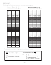
Reconnect the remaining wires according to the following chart.
Wire Color Function Terminal
Red Audio Output Red Binding Post
Black Output Ground Black Binding Post
Orange (two) High Voltage AC Bridge Rectifier AC
White High Voltage Center Tap CTI
Red High Voltage DC Positive + Red
Blue High Voltage DC Negative – BLUE
White/Blue Low Voltage Center Tap CT2
Blue (two) Low Voltage AC LV1, LV2