


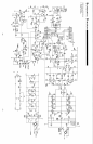
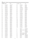
CIRCUIT OPERATION
trans•nova Implementation
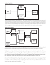
The transistor Q1 is configured to operate as a switch which controls the current source, Q103, of the input differential
amp, Q6 and Q7. When Q1 is off the emitter voltage is low turning off Q103. Timing of the Soft Start function is controlled
by the charging time of C29 through R13. The THERMAL Protection circuit uses Q1 to shut down the channel when
excessive heat is detected. The OVERLOAD protection switch Q5 and Q4 turn off Q3 directly when a short is detected
on the output.
U1A and U1B are buffer amps configured as unity gain, non-inverting voltage followers which feed the crossover filters
U7A and U7B. The feedback components which control the crossover functions are contained on the XCard plug-in
module. The output of the filters is fed to the attenuator network controlled by R24. The output of U2A and U7B is
connected to the input of the differential amp. U2B is configured as a DC servo integrator to null the input offset currents.
The output of the differential amp is fed to the driver stage by Q17 and Q18 which perform the DIABLO
transconductance steering function. The cascode pairs Q9, Q10 and Q11, Q12 supply the signal voltage and current
needed to drive the output stage Q30, Q31, Q32, Q33 and Q40, Q41, Q42, Q43. Class AB bias current is controlled
by R136. Loop feedback is supplied by the network R1 and C1, and global feedback by R10, C8 and C41.
Adjusting Bias:
The bias control establishes the quiescent Class AB output current of the amplifier. The bias should not need
readjustment from the factory setting; however, if the amplifier is repaired and output devices have been changed, or
if the two channels of the amplifier do not run at the same temperature, recalibrating the bias is necessary. Disconnect
the power to the amplifier before removing the cover. To adjust the bias, disconnect the input and speakers and remove
the jumper JW7. Connect an amp meter across the exposed pins. The correct polarity is marked adjacent to the jumper.
Adjust R136 to get a current reading of 400mA.
Calibrating Common Mode Rejection:
The input common mode null is adjusted by the trim pot R8. The CMRR should be greater than 75dB below rated output.
If the CMRR requires adjustment, feed the amplifier input with a common mode signal and adjust R8. Disconnect the
power to the amplifier before removing the cover. Use a sinewave generator set to 1 volt output at 1kHz. Connect the
generator signal output to the tip and ring of a 1/4" plug and ground to the sleeve. Plug this into the amplifier input.
Connect an AC voltmeter to the amplifier output binding posts. Adjust R8 to give the lowest voltage output from the
amplifier. For a temporary adjustment when a signal generator and voltmeter are not available, use an FM tuner and
tune it to an unused station as your signal source, and connect the output to the amplifier as described above. Connect
the amplifier output to a small full range speaker. Turn the amplifier level controls full down and turn the amplifier on.
Turn up the level control until you hear a signal through the speaker. Alternate between adjusting R8 for the lowest output
signal and increasing the input control until you have the level control full. There should be a very low output from the
amplifier if any is detected at all.
– 13 –