


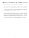

Thermal Protection
Temp
TS1, R25
Comparator
U5B
Soft Start Switch
Q1
THERMAL Indicator
CR2
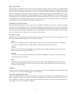
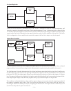
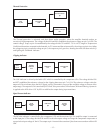
The Thermal protection is activated, and shuts down audio operation, when the amplifier heatsink reaches an
excessively high temperature. The voltage divider R22 and R23 establishes the reference voltage on pin 5 of U5B. The
control voltage, Temp, on pin 4 is established by the voltage divider TS1 and R25. TS1 is a NTC (Negative Temperature
Coefficient) thermistor, mounted on the heatsink. As TS1 warms and the resistance falls, the voltage on pin 4 rises. When
the voltage on pin 4 exceeds the voltage on pin 5, the output on pin 2 goes low, shutting down the Soft Start switch Q1
and lighting the THERMAL indicator.
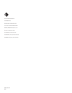
Clipping Indicator
CLIP Indicator
CR3
LED Driver
U5C
Clipping
Detector
U5A
Drive
Signal
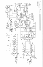
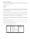
The CLIP indicator is driven by the buffer U5C which is controlled by the comparator U5A. The voltage divider R56
and R57 established the reference voltage for the clipping detector at pin 7 of U5A. The reference voltage scales the
output of U5A to indicate when the Drive Signal, at pin 6, demands in excess of the available voltage or current of the
output stage. The output of U5A is stretched by R55 and C30 to prevent the CLIP indicator CR3 from flickering. Hysteresis
is applied to the LED driver U5C by R53 to stabilize the output during input transitions.
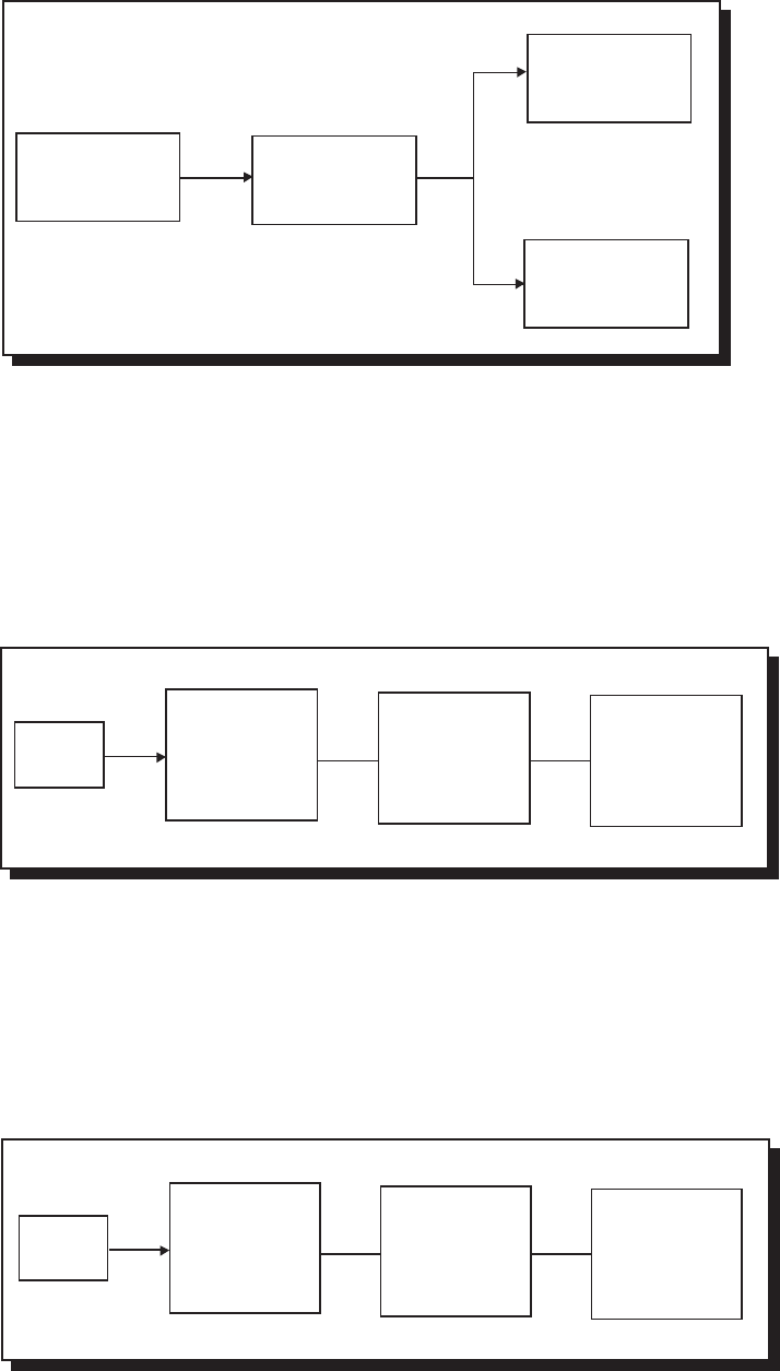
Signal Present Indicator
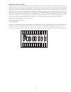
The SIGNAL indicator is controlled by the comparator U5D and the transistor Q8. The amplifier output is connected
to the input pin 9. The voltage divider R58 and R59 scales the output voltage to change the comparator output state at
an equivalent input voltage of 30mV. The output at pin 14 controls the transistor Q8 to shunt across and turn off the LED
CR4.
SIGNAL
Indicator
CR4
LED Driver
Q8
Signal
Detector
U5D
Amplifier
Output
– 15 –