


32
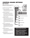
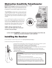
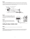
Determining The Mounting Position
of The Post Bracket Assembly
Step 1
With the gates closed, adjust the post bracket assembly and the gate
bracket until the opener is level. While holding the opener level, use
C-clamps to temporarily keep the post bracket assembly and gate
bracket in their respective positions on the fence post and gate.
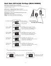
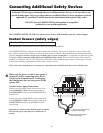
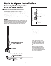
Push to Open Installation
Swinging gates shall not open into public access areas!
A "Push-to-Open" gate opens out from the property.
A Push-to-Open Bracket is required for this type of installation
(see
Accessory Catalog). If you have a pull-to-open gate (gate opens
into the
property), return to page 13; step 3.
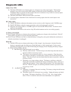
In a PUSH-TO-OPEN installation the openers are installed while the gates
are in the closed position.
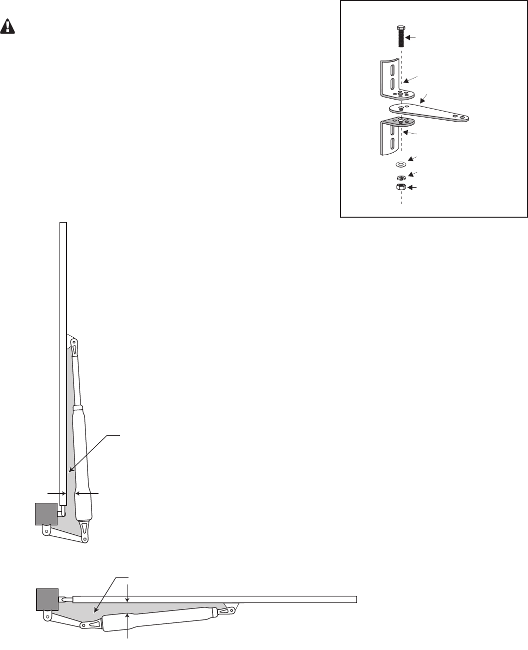
3/8" x 2" Bolt
3/8" Nut
Push-To-Open Bracket
(optional accessory)
Post Bracket
Post Bracket
3/8" Lock Washer
Post Bracket Assembly
3/8" Washer
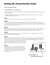
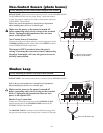
Step 2
After verifying that you have the best position
for the post pivot bracket, insert the
5
/16" x 1
3
/4"
bolt through the aligned holes of the post bracket
and post pivot bracket and fasten it with the
5
/16"
washer and nut.
IMPORTANT: If you loosened the clamp on
the post bracket to achieve the optimum position,
tighten it in its new position and recheck the gate
bracket with the gate in the open position (move the
gate bracket and re-clamp it if necessary).
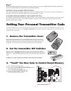
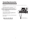
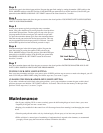
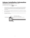
IMPORTANT: While determining the mounting point for the post
pivot bracket assembly be sure that the position allows for maximum
clearance between the gate and the opener in both the open and closed
positions, as shown in the diagrams below. This clearance will give the
opener the most efficient leverage point for opening and closing the gate
and more importantly provides the least possible pinch area.
Gate in the Closed Position
Pinch Area (gray)
Gate in the Open Position
Pinch Area (gray)
2" minimum
2" minimum