


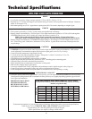
13
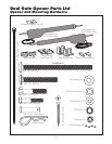
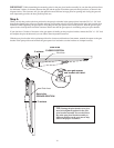
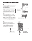
Clevis Pin
Hairpin Clip
Post Bracket Assembly
Bushing
Rear Mount
Opener
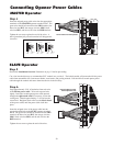
Clevis Pin
Hairpin Clip
Bushing
Gate Bracket
Front Mount
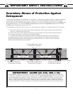
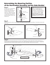
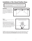
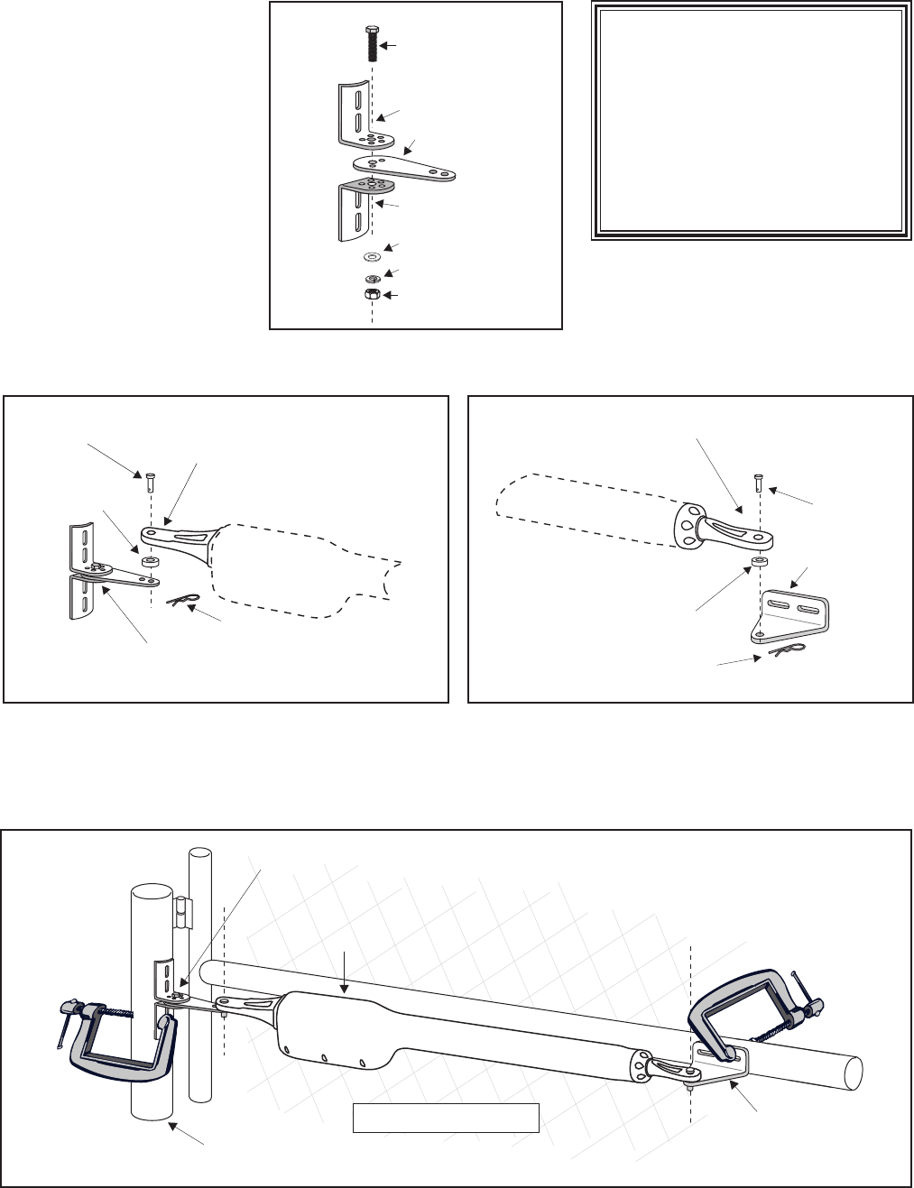
Determining the Mounting Position
of the Post Bracket Assembly and the Gate Bracket
Step 5
With the gate in the open position (up to 110º from its closed position), and the opener fully retracted, adjust the post
bracket assembly and gate bracket until the opener is level. While holding the opener level, use C-clamps to
temporarily
keep the post bracket assembly and gate bracket in their respective positions on the fence post and gate.
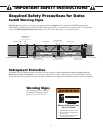
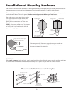
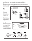
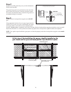
Step 3
Insert the
3
/8" x 2" bolt through
the center hole of the post
brackets and post pivot bracket
as shown. Fasten a
3
/8" lock
washer,
3
/8" washer and
3
/8" nut
on the end of the bolt. DO NOT
overtighten
the nut because the
post pivot bracket will have to be
adjusted later.
Step 4
Attach post bracket assembly and gate bracket to the opener with the clevis pins and bushings. Secure the clevis pins with
hairpin clips.
3/8" x 2" Bolt
3/8" Nut
Post Pivot Bracket
Post Bracket
Post Bracket
3/8" Lock Washer
Post Bracket Assembly
3/8" Washer
Level Opener
Fence Post
Gate In Open Position
LEVEL horizontal cross member
Post Bracket Assembly
Gate Bracket
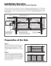
NOTE: The following steps are
intended for pull-to-open gate
installations. If you are mounting
your opener on a push-to-open gate
(e.g., a gate on a sloped driveway)
you will need to purchase a Push
To Open bracket
(see Accessory
catalog). Also, see
Push-to-Open
Installation beginning on page 30.