


14
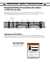
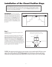
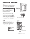
Gate in the
CLOSED POSITION
Pinch Area
Gate in the
OPENED POSITION
Pinch Area
2" minimum
2" minimum
Be sure gate opener
and bracket don't bind.
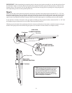
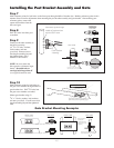
Step 6
When you feel that you have the best position for the post pivot bracket in the open position, insert the 5/16" x 1-3/4" bolt
through the aligned holes of the post bracket and post pivot bracket to hold it in place. Remove the clevis pin from the front
mount and while supporting the gate opener, swing the gate and gate opener to the closed position. With the gate and gate
opener in the closed position check the clearance and be sure that the gate opener is not binding at the post pivot bracket.
If you don't have 2 inches of clearance or the gate opener is binding on the post pivot bracket, remove the 5/16" x 1-3/4" bolt
and readjust the pivot bracket until you can achieve these important clearances.
With the post pivot bracket in the optimum position for clearance and freedom of movement, reattach the opener to the gate
bracket in the open position and recheck the gate opener level and make sure the brackets are clamped securely.
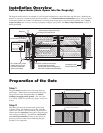
IMPORTANT: While determining the mounting point for the post pivot bracket assembly, be sure that the position allows
for minimum 2 inches of clearance between the gate and the opener in both the open and closed positions, as shown in the
diagrams below. This clearance will give the opener the most efficient leverage point for opening and closing the gate and
more importantly provides the least possible pinch area.
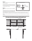
TIP: Turning the pivot bracket over gives
more hole alignment options for the post
pivot bracket assembly. You can also move
the entire post pivot bracket assembly to
different positions on the gate post to help
achieve the proper clearances.