


19
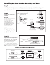
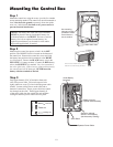
Step 2
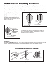
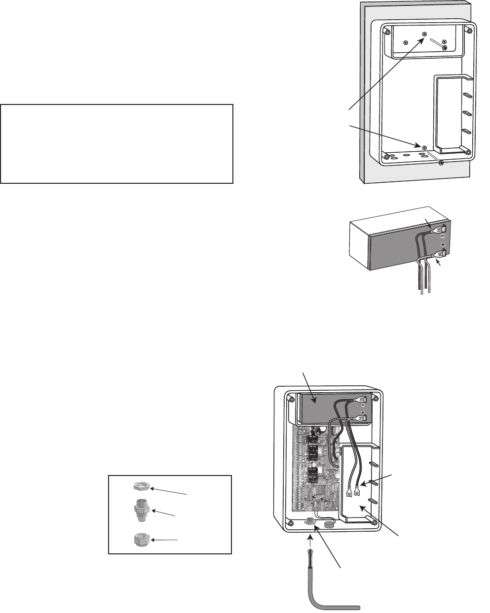
Make sure the control box power switch is in the OFF
position. The ON/OFF Switch is located on the bottom of
the control box. Remove the control box cover and slide
the battery into position with its terminals to the RIGHT
(see illustration). Connect the BLACK battery wire to the
NEGATIVE
(–) battery terminal. Connect the RED battery
wire to the POSITIVE (+) terminal. Pay close attention to
the color of the wires. If the wires are connected incorrectly,
the control board will be damaged
. NEVER insert the
battery with the terminals to the left.
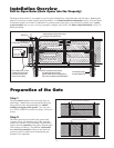
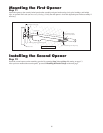
Mounting the Control Box
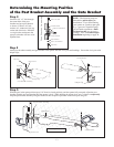
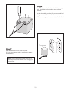
Step 3
Strip approximately
3
/16" of insulation from each
wire of the power cable. Twist each exposed wire
tightly (there are seven [7] wires inside the power cable
sheath). Loosen sealing nut on strain relief hub at
bottom of control box. Insert power cable into control
box through strain relief. Thread approximately 6"
of the power cable into the control box and retighten
sealing nut until the power cable locks into place.
Step 1
Mount the control box using the screws (provided) or another
secure mounting method. The control box must be mounted at
least 3 feet above the ground to protect it from rain splash,
snow, etc., and at least 3 feet from an AC power source to
prevent electrical interference
.
RED wire to POSITIVE (+) terminal
BLACK wire to NEGATIVE (–) terminal
RED
BLACK
Sealing Nut
Hub
Lock Nut
Strain Relief
Use mounting
holes and screws
provided to mount
control box to a
secure surface.
NOTE: The battery that came with your GTO/PRO,
MUST be placed in the top (horizontal) battery slot
with the terminals on the RIGHT. The extra (vertical)
battery slot is for an optional second battery. An
optional second battery can be used for solar and/or
high traffic applications, if needed..
Operator Power Cable
Strain Relief
Battery wires for
optional second battery.
12 Volt Battery
(included)
Space for optional
second 12 Volt battery
(see Accessory Catalog)