30
Refer to the sensor manufacturer’s instructions for information
about installing these devices on a vehicular gate.
Make sure the power to the opener is turned off
before connecting safety device wiring to the terminal
blocks. Unplugging the transformer does not turn
power to the opener OFF.
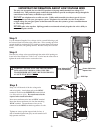
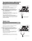
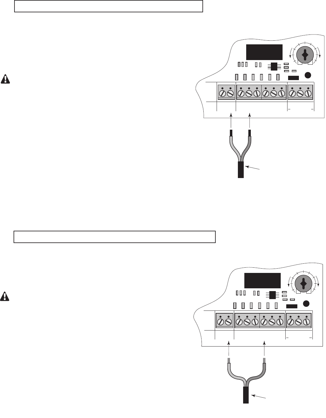
Non-Contact Sensor Connection:
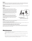
Connect one of the non-contact sensor dry contact output wires to the
COMMON (COM) terminal and the other to the SAFETY terminal
on the GTO/PRO SW2502 control board.
This input is ONLY monitored when the gate is
closing. Activating the non-contact sensor (obstructing
the safety beam path) will cause the gate to reverse to
the fully open position.
Non-Contact Sensors (photo beams)
The GTO/PRO SW2502 can also accept "Safety" input from normal-
ly open "dry-contact" output devices such as safety beams connected
to the SAFETY input terminal.
If not installing a non-contact sensor skip to next section.
PLEASE NOTE: Non-contact sensors are not included with the GTO/PRO SW2502.
Shadow Loop
If not installing a shadow loop skip to next section.
Refer to the sensor manufacturer’s instructions for information
about installing these devices on a vehicular gate.
Make sure the power to the opener is turned off
before connecting safety device wiring to the terminal
blocks. Unplugging the transformer does not turn
power to the opener OFF.
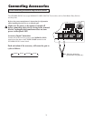
Shadow Loop Connection:
Connect one of the shadow loop wires to the COMMON (COM)
terminal and the other to the SHADOW LOOP terminal on the
GTO/PRO SW2502 control board.
The SHADOW LOOP is a detector located with the moving path of
the gate to prevent the gate from closing when a vehicle is in the path.
PLEASE NOTE: Non-contact sensors are not included with the GTO/PRO SW2502.
Wire from Non-Contact
Sensor (photo beam)
RECEIVER
COM COM
CYCLE
CLOSE
SAFETY
EXIT/
OPEN
SHADOW
LOOP
CLOSE
EDGE
OPEN
EDGE
BLKGRN RED
STALL FORCE
M
I
N
M
A
X
Wire from Shadow Loop
RECEIVER
COM COM
CYCLE
CLOSE
SAFETY
EXIT/
OPEN
SHADOW
LOOP
CLOSE
EDGE
OPEN
EDGE
BLKGRN RED
STALL FORCE
M
I
N
M
A
X


