VNR 100 • Panels and Cabling 10
c
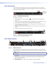
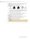
USB ports (2) — used to connect a mouse and keyboard for the initial configuration.
There are a total of four USB inputs: two rear panel and two front panel.
d
RS-232 Comm port — Insert 9-pin RS-232 cable.
e
Status LEDs — five LEDs, which provide information about:
Power
2
Network
Activity (2)
Network
Activity (1)
1
Drive
Activity
i
Ov
ertemperature
a. The Overtemperature (i) LED flashes yellow when a fan has failed. It lights yellow
solidly when the internal temperature is too high (the ambient temperature may be
too high or the flow of air to the fan may be obstructed).
b. Network 2 is not active, so this LED does not light.
c. The Network Activity (1) LED flashes green when there is activity on network 1.
d. The Drive Activity LED flashes yellow when the hard drive is in use.
e. The Power LED lights green when the unit is receiving power.
f
Reset button — use this button to reboot the VNR 100.
g
Power button — used to apply or turn off the main power. When the main power is
turned off, standby power is actively supplied to the recorder.
h
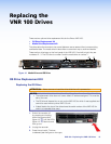
OS drive — houses the solid state operating system drive (removable).
i
Media drive — houses the media drive (removable).
j
Spare drive bays (2) — must not have drives fitted.
ATTENTION: Do not remove the OS or Media drive when the VNR 100 is powered
on.


