


QS-1USP 405 • Quick Start
USP 405
B-Y
SDI
Y
5421
H
V
OUT
Camera
PC Computer
Non-linear
Edit Station
RS-232
Control
Projector
Monitor
VCR
DVD
Monitor
Plasma
Display
2
A
M
A
X
1
0
0
-
2
4
0
V
5
0
-
6
0
H
z
RS-232
RGB/HD R-Y, B-Y, Y
RGB/R-Y, B-Y, Y
R-Y, B-Y, Y
RGB
B-Y
R-Y
VID
SDI
SDI
Y
RGB/R-Y, B-Y, Y
S-VIDEO
S-VIDEO
VIDEO
54
321
IN
R
/RY
G
/Y
B
/B-Y
H
V
S
R
/RY
G
/Y
B
/B-Y
HV
S
OUT
G
E
N
L
O
C
K
O
U
T
P
U
T
S
I
N
T
P
U
T
S
2
A
M
A
X
1
0
0
-
2
4
0
V
5
0
-
6
0
H
z
RS-232
RGB/HD R-Y, B-Y, Y
RGB/R-Y, B-Y, Y
R-Y, B-Y, Y
RGB
B-Y
R-Y
VID
SDI
SDI
Y
RGB/R-Y, B-Y, Y
S-VIDEO
S-VIDEO
VIDEO
54
321
IN
R
/RY
G
/Y
B
/B-Y
H
V
S
R
/RY
G
/Y
B
/B-Y
HV
S
OUT
G
E
N
L
O
C
K
O
U
T
P
U
T
S
I
N
T
P
U
T
S
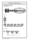
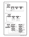
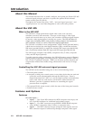
Application example with USP 405
being used as a scaler
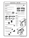
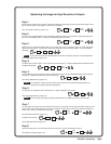
Quick Start — USP 405
Installation
Step 1
Turn off power to the USP 405 and the input and
output devices, and remove the power cords.
Step 2
Install the four rubber feet on the bottom of the
USP 405, or mount the USP in a rack.
Step 3
Attach input devices to the USP.
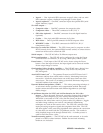
Rear panel video inputs
Input 1: RGB with buffered
local monitor
Input 2: RGB, component video, S-video, or
composite video
Inputs 3: composite video
Input 4: S-video
Input 5 (optional): SDI (serial digital interface)
Attach an SDI source to this BNC.
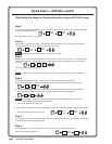
Step 4
Attach output devices to the USP 405.
Rear panel video outputs
Composite video (VID) output
Component video (R-Y, B-Y, Y) output
SDI video (serial digital interface)
output (optional)
S-video output
RGB or component video output
RGB or HD component video output
You can connect both outputs shown above
(15-pin HD connector and the BNCs)
simultaneously to two different displays. The
sync format is the same for both outputs.
Step 5
Plug the USP 405 and the input and output devices
into a grounded AC source, and turn on the input
and output devices.
Step 6
Use the LCD
menu screens
(see the next
page) or RS-232
programming
to configure the
USP 405. See
chapter two for
installation and
operation
procedures, and
see chapter
three for
programming
information.
RGB
1
I
N
P
U
T
S
2
VID
R
/R-Y
G
/Y
B
/B-Y
V
Y
C
2
VID
R
/R-Y
G
/Y
B
/B-Y
H
/HV
V
Y
C
2
VID
R
/R-Y
G
/Y
B
/B-Y
H
/HV
V
Y
C
2
VID
R
/R-Y
G
/Y
B
/B-Y
H
/HV
V
Y
C
2
VID
R
/R-Y
G
/Y
B
/B-Y
H
/HV
V
Y
C
2
VID
R
/R-Y
G
/Y
B
/B-Y
H
/HV
V
Y
C
RGBHV RGBS/RGBcvS RGsB
Composite VideoHDTV Component Video S-video
H
/HV
VIDEO
3
S-VIDEO
4
SDI
5
USP 405
2
A
M
A
X
1
0
0
-
2
4
0
V
5
0
-
6
0
H
z
RS-232
RGB/HD R-Y, B-Y, Y
RGB/R-Y, B-Y, Y
R-Y, B-Y, Y
RGB
B-Y
R-YVID
SDI
SDI
Y
RGB/R-Y, B-Y, Y
S-VIDEO
S-VIDEO
VIDEO
5
4321
IN
R
/RY
G
/Y
B
/B-Y
H
V S
R
/RY
G
/Y
B
/B-Y
HVS
OUT
G
E
N
L
O
C
K
O
U
T
P
U
T
S
I
N
T
P
U
T
S
SGI Computer
Betacam
Tape Deck
PC Computer
Non-linear Edit
Station
Sync
Timing Source
RS-232
Control
VCR
Monitor
USP 405
2
A
M
A
X
1
0
0
-
2
4
0
V
5
0
-
6
0
H
z
RS-232
RGB/HD R-Y, B-Y, Y
RGB/R-Y, B-Y, Y
R-Y, B-Y, Y
RGB
B-Y
R-YVID
SDI
SDI
Y
RGB/R-Y, B-Y, Y
S-VIDEO
S-VIDEO
VIDEO
5
4321
IN
R
/RY
G
/Y
B
/B-Y
H
V S
R
/RY
G
/Y
B
/B-Y
HVS
OUT
G
E
N
L
O
C
K
O
U
T
P
U
T
S
I
N
T
P
U
T
S
SGI Computer
Betacam
Tape Deck
PC Computer
RGB 112xi
Non-linear Edit
Station
Sync
Timing Source
RS-232
Control
VCR
Monitor
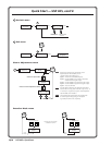
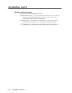
Application example with USP 405
being used as a scan converter
RGB/R-Y, B-Y, Y
S-VIDEO
SDI
R-Y, B-Y, Y
B-Y
R-Y
Y
VID
R
/R-Y
G
/Y
B
/B-Y
HVS
R
/R-Y
G
/Y
B
/B-Y
HVS
R
/R-Y
G
/Y
B
/B-Y
HVS
R
/R-Y
G
/Y
B
/B-Y
HVS
RGBHV RGBS
RGsB HDTV Component Video