


Installation and Operation, cont’d
USP 405 • Installation and Operation2-8
11
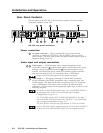
Color/Tint control button (Col/Tnt) — This button selects the color and tint
adjustment for the output display. The adjustment is made using the
horizontal Adjust and vertical Adjust adjustment knobs. The adjustment
range of color is 0 to 127, and tint is 0 to 255. See the “Image Adjustments”
section in this chapter.
The Color/Tint control affects only composite video and S-video.
12
Zoom control button — This button selects the zoom-in and zoom-out
adjustment for the output display. The adjustment is made using the
horizontal Adjust and vertical Adjust adjustment knobs. Turning either
adjustment knob clockwise will zoom in on the image, and turning either
knob counterclockwise will zoom out on the image. See the “Image
Adjustments” section in this chapter.
13
Detail control button — This button selects the image detail (sharpness)
adjustment for the output display. The adjustment is made using the
horizontal Adjust and vertical Adjust knobs. The sharpness adjustment
compensates for long cable runs. The horizontal Adjust knob controls the
horizontal filter and the vertical Adjust knob controls the vertical filter. The
adjustment range of each knob is 0 to 7. See the “Image Adjustments”
section in this chapter.
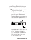
LCD menu display and controls
14
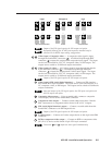
LCD — This screen displays configuration menus and status information.
See the “Menus, Configuration, and Adjustments” section in this chapter
for details.
15
Menu button — Use this button to enter and move through the main menu
system in the USP 405. See the “Menus, Configuration, and Adjustments”
section in this chapter for details. This button is always lit yellow.
16
Next button — Use this button to step through the submenus in the USP
405 menu system. See the “Menus, Configuration, and Adjustments”
section in this chapter for details. This button is always lit yellow.
17
Horizontal Adjust ( ) knob — Rotate this knob to scroll through menu
options and make adjustments.
18
Vertical Adjust ( ) knob — Rotate this knob to scroll through menu
options and make adjustments.
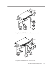
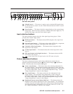
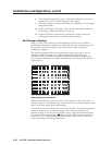
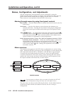
Genlock and Vertical Interval Switching
For vertical interval switching (to allow clean switching between signals from
several devices during the vertical blanking period of each signal), a composite
sync signal can be applied at the Genlock In connector, and can also be passed to
another device via the Genlock Out connector.
If the genlock connectors are used only for vertical interval switching, no
horizontal or subcarrier phase adjustments are required.
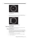
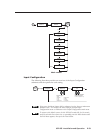
Genlock setup
Genlock differs from simple vertical interval switching in that an external device
(a black burst generator) generates a reference sync signal for the system, and
every device that uses that signal has its output signal’s horizontal and
subcarrier phases adjusted to exactly match that of the generator. This allows
precise timing and full synchronization. Genlocked systems produce cleaner
switches between inputs than do those without this type of synchronization.