


2-9USP 405 • Installation and Operation
An oscilloscope is required for genlock setup, and a vectorscope is
recommended. Waveform monitors of types other than a vectorscope may give
the appearance that timing is adjusted correctly when it is 180 degrees out of
phase. This results in incorrect colors or picture artifacts.
To synchronize the USP 405’s video output with a genlock signal, follow these
steps:
All equipment in the system must be powered up and turned on for at least
15 to 20 minutes before genlock setup adjustments can be made and before
the equipment is used in a genlocked application.
1. Power up and turn on all the devices that will use the genlock signal.
The devices must be on for at least 15 to 20 minutes before proceeding
with any adjustments.
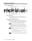
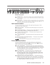
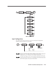
2. Connect the active timing source signal to the Genlock In connector on
the rear panel.
3. Connect the video input signals to the USP 405, as described
previously in this chapter.
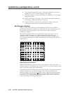
4. Connect the oscilloscope (“scope”) probe A to the Genlock Out
connector. This provides the scope’s reference signal. In order to avoid
altering the genlock signal, use the cabling configuration that will be
used in the installation. Either connect the genlock signal cable from
the scope to the next device in the system to be timed, or provide 75
ohm termination at the scope’s genlock output.
REMOTE
RGB/HD R-Y, B-Y, Y
R-Y, B-Y, Y
B-Y
R-YVID SDI
Y
RGB/R-Y, B-Y, Y
S-VIDEO
IN
R
/R-Y
G
/Y
B
/B-Y
HVS
OUT
G
E
N
L
O
C
K
O
U
T
P
U
T
S
Timing Source
OUT
To Scope
Probe A
75 ohm Terminator
To Scope Probe B
5. Connect scope probe B to the USP 405’s composite video output
connector.
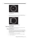
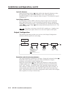
6. Using the instructions for the scope you are using, set the scope to view
the signal’s horizontal phases. Adjust the horizontal phase by rotating
the horizontal Adjust (
) knob (see the “Genlock Menu” section in
this chapter). Adjust the horizontal phase until there is no (0°)
difference between the composite video output’s horizontal sync phase
and the genlock signal’s horizontal phase. See the “Oscilloscope
displays” section in this chapter.
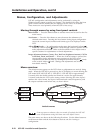
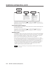
7. Set the scope to view the subcarrier signals. Adjust the sub phase by
rotating the vertical Adjust (
) knob until there is a zero phase
difference between the genlock signal and the NTSC/PAL output (see
the “Genlock menu” section in this chapter).