


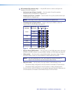
Receiver Rear Panel Features
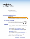
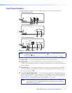
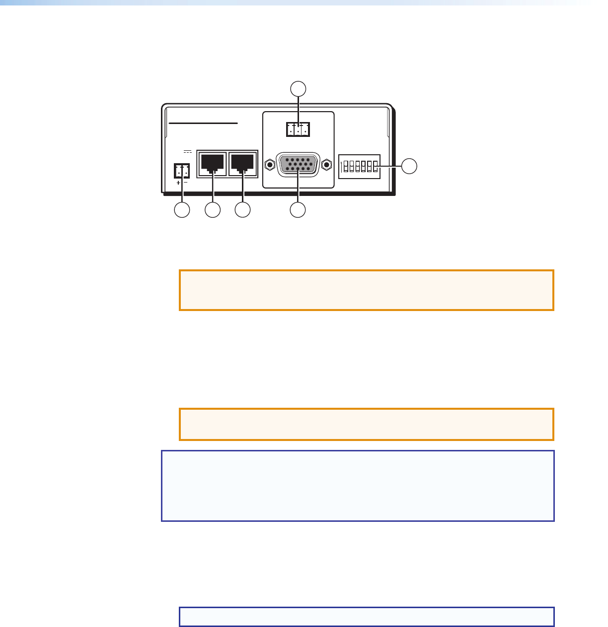
Figure 6 shows an MTP RL 15HD RS receiver, which has all of the connectors and other
features that are on either receiver in the MTP 15HD RS series.
INPUT
BUFFERED
OUTPUT
POWER
12V
.5A MAX
MTP RL 15HD RS
ON
1 2 3 4 5 6
H SYNC +
V SYNC +
C SYNC
SOG
VIDEO
END UNIT
OUTPUT
Tx Rx
RS-232
G
5
1 2
3
4
6
Figure 6. Receiver Rear Panel
a
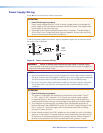
Power connector — Plug the included external 12 VDC power supply into this 2-pole
captive screw connector. Wire the connector as shown in figure 8 on page 12.
ATTENTION: Potential damage to property.
Before wiring the connector, read the notes, attentions, and warnings in the
"Power Supply Wiring" section on page 12.
b
Input connector — Connect one end of the twisted pair cable from the transmitter or
from the buffered output connector of an RL receiver to this RJ-45 female connector.
c
Buffered output connector — Connect one end of a twisted pair cable to this female
RJ-45 connector. Connect the free end of the same TP cable from the receiver to the
Input RJ-45 female connector on another receiver.
See "Twisted Pair Cable Termination" on page 13 to wire the RJ-45 connectors.
ATTENTION: Potential damage to property.
Do not connect these devices to a computer data or telecommunications network.
NOTES:
• The non-C7 transmitters and receivers will not work properly with STP201 or CAT 7
STP cable.
• The C7 transmitters and receivers will work properly only with STP201 or CAT 7 STP
cable.
d
Output video connector — Connect a projector or other high resolution video device
to this 15-pin HD connector.
e
RS-232 connector — Connect a serial communications port to this 3.5 mm, 3-pole
captive screw connector for bidirectional RS-232 communication. Wire the connector as
shown in figure 5 on page 8.
NOTE: See
d
on page 8 before wiring the connector.
MTP 15HD RS Series • Installation and Operation 10