


Transmitter Rear Panel Features
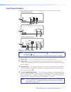
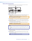
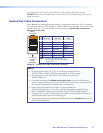
Figure 3 shows an MTP T 15HD RS transmitter, which has all of the connectors and other
features that are on either transmitter in the MTP 15HD RS series.
OUTPUT
INPUT
POWER
12V
.5A MAX
Tx Rx G
RS-232
MONITOR
PRE-PEAK
ON
OFF
MTP T 15HD RS
65
1
32
4
Figure 3. Transmitter Rear Panel
a
Power connector — Plug the included external 12 VDC power supply into this
2-pole captive screw connector. See "Power Supply Wiring" on page 12 to wire the
connector.
b
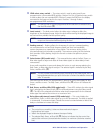
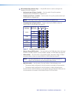
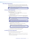
Input video connector — Connect a computer video source to this 15-pin HD
connector for high resolution video input (see figure 4).
51
15 11
610
Female
Figure 4. 15-pin HD Connector
NOTES:
• Input only sync signals (no video signals) on the sync pins (13 and 14).
• For component video, use the R (R-Y) and R return pins (pins 1 and 6),
G (Y) and G return pins (pins 2 and 7), and B (B-Y) and B return pins
(pins 3 and 8). For S-video, use the R, R return (C-chroma), G, and
G return (Y-luma) pins.
• For composite video, use the G pin and the associated return pin. For additional
genlocked video signals, use the R, B, and associated return pins.
c
Monitor connector — Connect a video monitor to this 15-pin HD connector for
buffered, high resolution video loop-through.
d
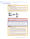
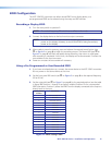
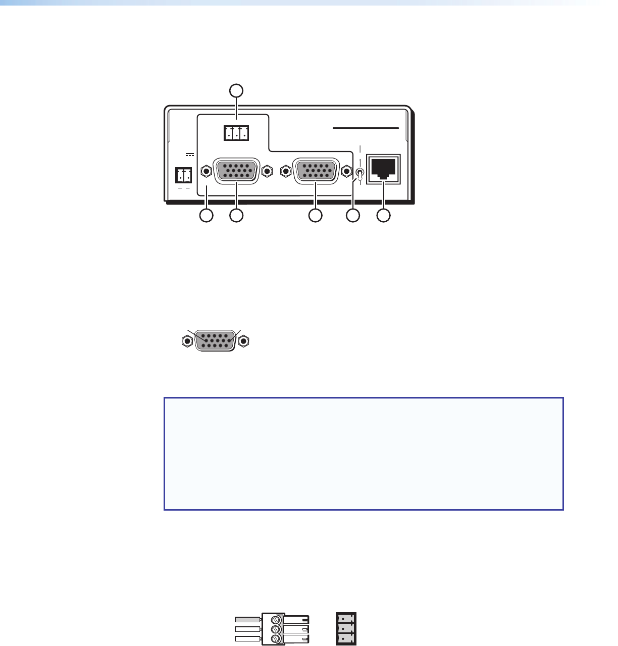
RS-232 connector — Connect a serial communications port to this 3.5 mm, 3-pole
captive screw connector for bidirectional RS-232 communication.
Wire the connector as shown in figure 5.
Ground
Tx
Rx
G
Receive
Transmit
Connected RS-232
Device Pins
MTP
Pins
Figure 5. RS-232 Connector Wiring
MTP 15HD RS Series • Installation and Operation 8