


2. Use the DTMF keypad or use the Recall Telephone
Number key (RCL) to enter the digits of the tele-
phone number.
3. Press the secondary key and then press the
SEND key. An optional tone (sidetone) may be
heard as each digit is transmitted.
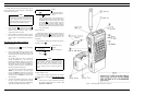
4. When someone answers, press the PTT bar and
speak directly into the grille on the radio, or across
the face of an external microphone. Release the
PTT bar as soon as you stop talking. Messages can
not be received when the PTT bar is pressed.
5. When the conversation is completed, press the (#)
key to disconnect from the telephone system.
To Recall a Telephone Number:
The RCL button is used to recall the last number dialed
or to recall one of the ten 16-digit numbers that can be stored
in memory.
To Recall the Last Number Dialed:
1. Press the secondary key and then the RCL
button.
2. Then press the secondary key and then the SEND
key as in Step 3 of To Make a Telephone Call.
To Recall a Telephone Number Stored in Memory:
1. Press the key number of the memory location (1
through 9).
2. Press the secondary key and then the RCL
key.
3. Press the secondary key and the SEND key as in
Step 3 of To Make a Telephone Call.
SYSTEM ANALYSIS
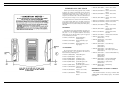
Ericsson GE M-PD Personal radios are two-way, FM ra-
dios designed for public communications. The M-PD Sys-
tem radio consists of four printed wire boards as follows:
• Radio Board: carries the transmit, receive and fre-
quency synthesizer circuits
• Control Board: supports logic, control and audio
processor circuits
• Display Board: carries LCD displays
• Signaling Board: provides additional software con-
trolled signaling functions
Interconnection of the control board with other boards
and control circuits is made with flexible circuit boards and
connectors. All control leads which are "barred", such as
PTT, mean that the function indicated occurs when the lead
is in a low voltage condition.
Circuit illustrations shown in the following text are sim-
plified representatives of actual circuits. They are intended
only to illustrate basic circuit functions.
RADIO BOARD
Transmit Circuits
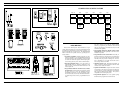
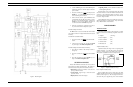
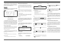
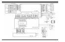
The M-PD transmit circuit, as shown in Figure 2 - Block
Diagram, consists of the following integrated circuit mod-
ules:
• Amplifier (TX-Amp)
• Power Amplifier (PA)
• Power Controller (PC)
• Antenna Switch (AS)
• Filter Network (FN)
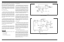
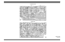
Amplifier Module (A201):
Amplifier module (TX-Amp) A201 is a single stage RF
amplifier hybrid IC. A 0 dBm RF signal on the input will
produce a +23 dBm signal on the output (refer to Figure 3).
This module is broadband and does not require tuning.
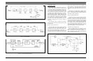
Power Amplifier Module (A202):
Power Amplifier (PA) A202 is a three stage, wide band
amplifier module with an input and an output impedance of
50 ohms (refer to Figure 4). The first stage of the PA mod-
ule has the DC power supplied by power control transistor
Figure 2 - Block Diagram
Figure 3 - Amplifier Module (TX-Amp)
LBI-31629
5