


• Channel Busy Lock Out: Personality information in-
cludes the capability to prevent the transmitter from op-
erating on a channel where carrier activity is present.
The "Channel Busy" indicator (BSY) is active during
this time.
• Automatic/Manual Power Levels: The desired power
level on each channel can be programmed into the radio
personality such that it is automatically selected channel-
by-channel or selected manually.
• Home Channel Feature: A "Home" channel can be pro-
grammed into the radio which is selected by pressing the
"Home" button. This allows a user to quickly reach a
reference channel.
• Surveillance Feature: In addition to the ability to pro-
gram the display 1ighting on or off per channel, the side-
tone beep related to the operation of a radio control is
capable of being disabled on a channel by channel basis.
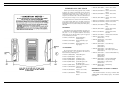
• Eight Character Alphanumeric Liquid Crystal Dis-
play: This display is used to exhibit the condition of the
radio. It shows: Channel Designation, Signaling
ON/OFF, Transmit, Volume Level, Battery Condition,
Channel Busy, High/Low Power output, SCAN 0N/0FF
and Priority 1 & 2.
• Simple Remote Control Capability: By connection
through the UDC (Universal Devices Connector) a sim-
ple speaker/ microphone can be operated which can also
control PTT and Volume level.
• Push Button Controls Only: All control functions on
the radio, with the exception of the power ON/OFF
switch, are operated through push button controls on the
top and sides of the radio.
• Programmable through UDC: The entire personality
of the radio is programmed into the radio through the
UDC through four connections. The Ericsson GE
TQ2310 Universal programmer is one method of pro-
gramming the radio, while the capability exists to inter-
face to an RS-232 device at a maximum of 1200 baud.
• Keyboard Enable: Pressing two keypad keys (Secon-
dary Function and KEY BD) in sequence activates the
front DTMF keyboard. The user can then change radio
functions as required. The top keypad is not protected in
this manner for ease of using the frequently switched
functions (volume, channel, Signaling On/Off, . . .etc.).
• Two-Tone Sequential Encode/Decode: Selective call-
ing encode, decode or encode/decode is enabled or dis-
abled on each individual channel. Three simultaneous
unique decodes are available for each channel to allow
large systems the capability for individual and group
calls.
Compatibility with Channel Guard, Digital Channel
Guard, GE-STAR, DTMF, Dual Priority and Scan are
maintained. Various audible alerting signals are avail-
able on choice when programming the radio.
• DTMF Encode Reperatory Dialing: When enabled by
the information programmed into the personality of the
radio, the DTMF encode function can be used by either
manually dialing from the keypad or by recalling a com-
plete number stored in memory. Ten stored numbers, in-
cluding the 1ast number dialed, up to 16 digits are easily
recalled to the display for viewing. A convenient display
overflow and shift mechanism is incorporated into the
display control procedure.
It is not necessary to press the PTT switch while dialing.
Features needed for overdialing, autopatch and paging
terminals, including programmed delays, pauses and the
generation of the "*" and "#" DTMF pairs are included.
• Programmable Dual-Priority Scan: The radio is pro-
grammed to listen to a selected channel while scanning
back to two priority channels. The radio reverts to the
priority 1evel channels should any activity occur on
those channels. There are two 1evels of priority. The
first priority channel takes precedence over the second
priority channel and the second priority channel takes
precedence over the user selected channel.
• Manual High/Low Power Selection: If programmed
into the radio, the user will be able to manually select
either high or low RF power output through the front
panel keyboard.
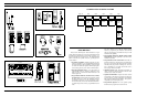
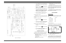
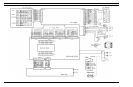
Physically an M-PD radio consists of three printed wire
board assemblies and a battery pack as follows:
a. A printed wire board specially shielded with zinc
alloy on which the radio assembly (transmit/re-
ceive/synthesizer) is assembled.
b. A Logic control board containing the microproc-
essor.
c. A Display board carrying various display and in-
dicating circuits.
d. A battery pack that fits the M-PD main unit.
e. Light weight metal front and back housing.
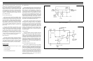
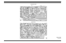
Radio Assembly
Transmit:
The transmit circuit is made up of four major circuits as
follows:
a. Wideband Hybrid Exciter: Amplifies the signal
from the frequency synthesizer with about 21
dB gain.
b. Wideband Power Amplifier: Amplifies the out-
put signal of the exciter (13 dB to 18 dB) to the
desired output level for transmission.
c. Wideband Power Control Hybrid IC: Can re-
duce the transmitter output level by 10 dB.
d. Output Low pass Filter (LPF): Consists of a
three stage LPF to eliminate higher harmonics.
The transmitter completely covers the band within the
split with no adjustments except for the RF power control
voltage from the controller.
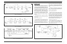
Receive Circuit:
The receiver consists of three major circuits as follows:
a. Front End Circuit: Consists of single stage pre-
amplifier with about 12 dB gain and the pre
BPFs and the post-BPFs of the pre-amplifier.
b. First Mixer and IF Circuit: A special double
balanced mixer provide a 45 MHz first IF,
which is coupled through band pass filter
(BPF) and an IF amplifier to get the desired
first IF signal.
c. Second IF (455 kHz): Consists of one IC and
one BPF, containing the second mixer, second
IF amplifier and FM detector. The second IF
output provides the Logic section with audio
output.
Frequency Synthesizer:
The frequency synthesizer is made up of three major
modules as follows:
a. VCO Module: The VHF band frequency syn-
thesizer has two VCO’s, one for transmitting
and one for receiving. The transmitter is
modulated at both the VCO and the VCTCXO.
b. VCTCXO Module: The VCTCXO is a tem-
perature compensated crystal oscillator to pro-
vide a 13.2 MHz reference frequency and has
modulation capability.
c. Phase Lock Loop: Consists of a frequency di-
vider and a low current drain C-MOS IC for
phase comparison.
Logic Circuit
The Logic circuit consists of a LCD board, a signaling
board and a control board with an audio IC as follows:
a. LCD Board: Includes LCD driver circuits for
the display.
b. Signaling Board: Includes a CMOS microcom-
puter, an audio amplifier and a comparator cir-
cuit. This board provides DTMF and GE STAR
encoding, sequential Two Tone decoding and
control for the SCAN operation.
c. Control Board: Carries a microprocessor, a bat-
tery backed RAM, audio circuit and I/O inter-
connections with the frequency synthesizer and
the display. Thus, this board commands all the
functions and operation of the M-PD radio.
d. Audio IC: Includes transmitter and receiver
audio circuits.
Power Supply
The M-PD battery pack connects to the bottom of the M-
PD radio to supply 7.5 Volts DC to the unit. The battery
packs are available in three capacities: standard, high and ex-
tra high. To charge these battery packs, charges are available
in three different styles: a desk charger, a wall mount multi-
charger and a vehicular charger.
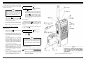
OPERATION
The M-PD Personal Radio is delivered disassembled into
three parts:
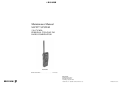
1. M-PD Radio (Main Unit)
2. Antenna
3. Battery Pack
LBI-31629
3