


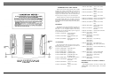

Charger combinations for charging the battery packs are
available with charge times of 1 hour, 3 hours and 16 hours. A
combination can be a single unit desk or a vehicular charger. It
can also be a wall mounted multiple charger.
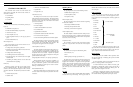
Charge Level
A fully charged battery pack should provide a terminal
voltage greater than 7.5V. A fully discharged battery pack
should provide a reading of no less than 6V.
MAINTENANCE
This Maintenance section provides information on adjust-
ments of the radio (transmit, receive and synthesizer), preven-
tive maintenance and a Disassembly Procedure. Information is
also provided for removing and replacing chip components and
module replacement. The Service Section, listed in the Table
Of Contents, provides a more complete set of alignment proce-
dures for the radio plus a detailed Troubleshooting Procedure.
INITIAL ADJUSTMENT
After the radio has been programmed, as described in Pro-
gramming Instructions (LBI-31635), the following adjustments
should be made by a certified electronics technician.
Transmit Circuit Alignment:
The transmit circuit is factory tuned and should not require
any readjustment. The frequency and modulation should be
measured and recorded for future reference.
Receive Circuit:
No initial adjustments to the receive circuit are required.
Synthesizer Circuit:
No initial adjustments to the synthesizer are required.
PREVENTIVE MAINTENANCE
To ensure a high operating efficiency and to prevent me-
chanical and electrical failures, routine checks should be per-
formed of all mechanical and electrical parts at regular
intervals. Preventive maintenance should include the following
checks:
Antenna:
The antenna and antenna contact should be kept clean, free
from dirt or corrosion. If the antenna or contact should be-
come dirty or corroded, loss of radiation and a weak signal will
result.
Mechanical Inspection:
Since portable radio units are subject to shock and vibra-
tion, check for loose plugs, nuts, screws and other parts to
make sure that nothing is working loose.
Alignment:
The transmit and receive circuit meter readings should be
checked periodically and the alignment "touched up" when
necessary. Refer to the applicable alignment procedure and
troubleshooting sheet, found in Service Section LBI-31677, for
typical voltage readings.
Frequency Check:
Check transmit frequency and deviation. Normally, these
checks are made when the unit is first put into operation. They
should be repeated after the first month of operation, then
again one time each year.
DISASSEMBLY
To gain access to the Radio board (transmit, receive and
synthesizer circuits) or Control Board for servicing, disassem-
ble as follows:
Radio Board: Step 1 through Step 4
Controller Board: Step 5 through Step 7
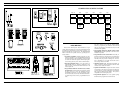
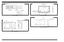
Disassembly Procedure (See Figure 11):
Equipment Required:
• Small Phillips-head screwdriver
• Small flat-blade screwdriver
• Needlenose pliers
• Allen-head wrench for removing set screws
• Pencil-type soldering iron (25-40 Watts) with a fine tip
Step 1:
To gain access to the radio, loosen, but do not remove,
the four captive screws shown at and . Carefully re-
move the back cover. For normal radio alignment, the back
cover is all that needs to be removed. When tightening the
captive screws, they should be no tighter than 4 0.5 inch-
pounds. (See Figure 12)
Step 2:
To remove the Radio Board, unscrew and remove the an-
tenna at and RF connector at . Remove the six
screws at using the Phillips-head screwdriver. The radio
portion can now be detached from the rear cover. (See Fig-
ure 13)
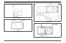
Step 3:
Remove the shield cover from the eggcrate. (See
Figure 14)
Step 4:
To remove the antenna changeover switch, remove the
tap screw at using the Phillips-head screwdriver. Unsol-
der the antenna switch lead connection at . The antenna
switch assembly can now readily be removed by hand. (See
Figure 15)
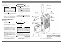
Step 5:
To remove the Controller Board remove the five screws
at from the Controller board. Use the Phillips-head
screwdriver. (See Figure 16)
Step 6:
Unplug the LCD control flex circuit at from the con-
nector at . The Controller Board can now readily be re-
moved from the LCD board. (See Figure 17)
Step 7:
To remove the LCD Board, pull the contact Pins at
out of the socket in the MIC flex circuit. Remove the seven
screws at , using the Phillips-head screwdriver. The LCD
board can now be readily removed. (See Figure 18)
REPLACEMENT
The major components of the M-PD Personal Radio are
the PA, TX-AMP (driving amplifier), PC (Power Control
Module), VCO (Voltage Controlled Oscillator) and the
VCTCXO (Ref. Osc.). These are very reliable devices and
will not normally need to be replaced. Before replacing any
of these modules, always check out the associated circuitry
carefully.
To remove any of these major components, refer to the
applicable replacement procedure found in the Service Sec-
tion (LBI-31677).
TROUBLESHOOTING PROCEDURE
Maintenance of the M-PD Personal Radio is faciliated by
using the Troubleshooting Procedures and service techniques
unique to this radio. The Troubleshooting procedures are
designed to quickly lead the serviceman to the defective cir-
cuit or component. These procedures are found in the Serv-
ice Section.
WEATHERPROOF INTEGRITY
The M-PD radio is designed to meet MI-810-D specifi-
cation for Blowing Rain. All access to the M-PD radio are
protected from water entry by suitable gaskets and seals.
However, degradation due to use, or disassembly during re-
pairs, may affect the integrity of the seals as provided by fac-
tory assembly. A maintenance procedure is provided in the
Service Section (LBI-31677) to assure that the radio housing
will continue to meet the weatherproof features as designed.
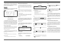
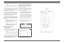
Figure 10 - Battery Pack
To prevent loss of memory in RAM A2 on the Control-
ler Board, lithium battery BT1 should be replaced at
three years. A procedure for changing BT1 is provided
in Service Section LBI-31677.
WARNING
ALWAYS remove the battery pack before removing
any component board to avoid blowing the fuse.
CAUTION
LBI-31629
9