


Reference Manual
00809-0100-4514, Rev BA
January 2008
Rosemount 1154
www.rosemountnuclear.com
Section 4 Operation
Overview . . . . . . . . . . . . . . . . . . . . . . . . . . . . . . . . . . . . . . . page 4-1
Transmitter Operation . . . . . . . . . . . . . . . . . . . . . . . . . . . . page 4-1
The
δ-Cell Sensor . . . . . . . . . . . . . . . . . . . . . . . . . . . . . . . .page 4-3
Demodulator . . . . . . . . . . . . . . . . . . . . . . . . . . . . . . . . . . . . page 4-3
Linearity Adjustment . . . . . . . . . . . . . . . . . . . . . . . . . . . . . page 4-3
Oscillator . . . . . . . . . . . . . . . . . . . . . . . . . . . . . . . . . . . . . . . page 4-4
Voltage Regulator . . . . . . . . . . . . . . . . . . . . . . . . . . . . . . . .page 4-4
Zero and Span Adjustments . . . . . . . . . . . . . . . . . . . . . . . page 4-4
Current Control . . . . . . . . . . . . . . . . . . . . . . . . . . . . . . . . . .page 4-4
Current Limit . . . . . . . . . . . . . . . . . . . . . . . . . . . . . . . . . . . . page 4-4
Reverse Polarity Protection . . . . . . . . . . . . . . . . . . . . . . . . page 4-4
OVERVIEW This section provides brief descriptions of basic transmitter operations in the
following order:
• Transmitter Operation
• The ␦-Cell
™
Sensor
• Demodulator
• Linearity Adjustment
• Oscillator
• Voltage Regulator
• Zero and Span Adjustments
• Current Control
• Current Limit
• Reverse Polarity Protection
TRANSMITTER
OPERATION
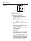
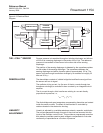
The block diagram in Figure 4-2 on page 4-3 illustrates the operation of the
transmitter.
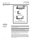
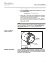
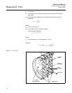
The Rosemount 1154 Alphaline Pressure Transmitters have a variable
capacitance sensing element, the δ-Cell (Figure 4-1 on page 4-2). Differential
capacitance between the sensing diaphragm and the capacitor plates is
converted electronically to a 2-wire 4–20 mA dc signal.
Where:
P is the process pressure.
PK
1
C
2
C
1
–
C
1
C
2
+
--------------------
⎝⎠
⎜⎟
⎛⎞
=