


Reference Manual
00809-0100-4514, Rev BA
January 2008
2-3
Rosemount 1154
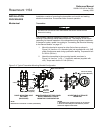
Transmitters with Flange Options A, D, H, J, L, or M are shipped with
Swagelok fittings for process connections. Included are front ferrule, rear
ferrule, and nut. Ensure that the fittings are placed on the tubing with the
orientation and relative position shown in Detail A, Figure 2-5 on page 2-7.
Process tubing used is
3
/8-inch outside diameter, and of suitable thickness for
the pressure involved.
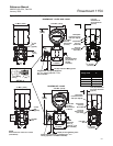
The connections can be loosened and re-tightened 20-30 times without
compromising the leak proof seal. To reconnect, insert the tubing with
pre-swaged ferrules into the fitting until the front ferrule sits in the fitting.
Tighten the nut by hand, then rotate one-quarter turn more or to the original
one-and-one-quarter tight position. Then snug the nut slightly with a wrench.
For more information regarding the use of Swagelok tube fittings, refer to:
Fittings Catalog MS-01-140
“Gaugable Tube Fittings and Adapter Fittings”
www.swagelok.com
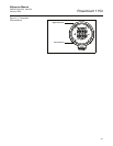
If the drain/vent valves must be opened to bleed process lines, torque them to
7.5 ft-lb (10 N-m) when closing.
Proper location of the transmitter with respect to the process tubing depends
on various process parameters. When determining the best location, consider
the following:
• Keep hot or corrosive fluids from contacting the transmitter.
• Prevent sediment from depositing in the impulse tubing.
• Ambient temperature gradients and fluctuations can result in erroneous
transmitter readings.
• Keep impulse tubing as short as possible.
• For differential transmitters, balance the liquid head on both legs of the
impulse tubing.
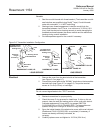
• For liquid flow or pressure measurements, make taps on the side of the
line to avoid sediment deposits, and mount the transmitter beside or
below the taps so gases vent into the process line (see Figure 2-6 on
page 2-8).
• For gas flow or pressure measurements, make taps on the top or side
of the line and mount the transmitter beside or above the taps so liquid
drains into the process line (see Figure 2-6 on page 2-8).
• For steam flow or pressure measurements, make taps on the side of
the line, and mount the transmitter below the taps so the impulse tubing
stays filled with condensate (See Figure 2-6 on page 2-8).
• For steam service, fill the lines with water to prevent steam from
contacting the transmitter. Condensate chambers are not necessary
since the volumetric displacement of the transmitter
is negligible.