


Dolby Installation Guidelines Unit Connections and Dimensions
2-15
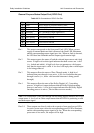
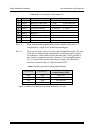
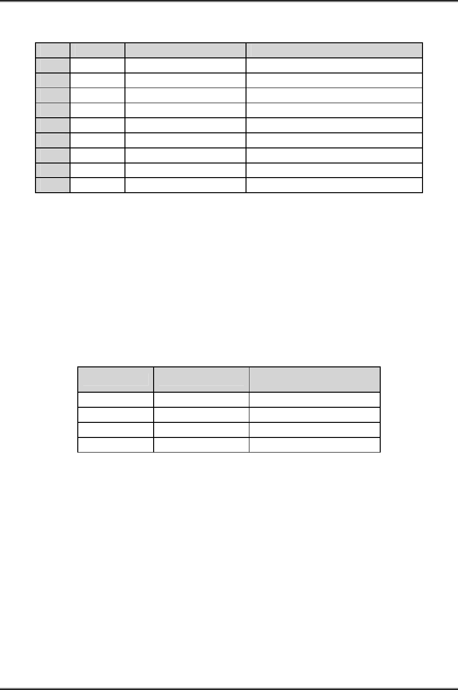
Table 2-10 Pin Connections for the Status Port
Pin Direction Connection Comments
1
Output Dolby E Detect 1: Dolby E 0: PCM or none
2
Output Reference Video Valid 1: Valid; 0: Ref video error
3
Output Dolby E Decoding Valid 1: Valid; 0: Decoding error
4
Output System Operational 1: Functional 0: Failed
5
Output Fault 1: Functional 0: Hardware Fault
6
Output Reserved —
7
Input PCM channel routing Voiceover and Switched mode
8
Input PCM channel routing Voiceover and Switched mode
9
N/A Ground —
Pins 1–5 These indicate details regarding the current condition of the unit. A “1”
corresponds to a “high” level on the corresponding pin.
Pins 7–8 These can be used to select Voiceover and Switched Out modes. The state
of the pins is normally high (internal pull up), and they detect a high-to-
low transition. A held contact closure between pins 7 and 9 (ground) or
pins 8 and 9 is required to activate a function. A low-to-high transition
(i.e., a switch release) restores the delay out setting. The table below
shows the function of the two GPI pins on the DP572.
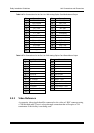
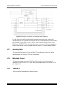
Table 2-11 Status port Output Routing Mode Selection
Ctrl in Pin 8 Ctrl in Pin 7
PCM Chan Config
Output Routing Mode
High High Delay Out
High Low Voiceover
Low High Switched Out
Low Low Reserved
Figure 2-5 details the channel routing of these modes for a 5.1 input.