


Dolby Installation Guidelines Unit Connections and Dimensions
2-14
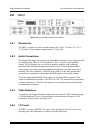
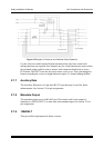
AES3-id signals are very similar to analog composite video, although dedicated
AES3 distribution equipment should be used. If the loop-through BNC connectors are
not being used to feed additional equipment, terminate them with a standard 75Ω
video terminator. The PCM delay input is of the same specification as the main input,
except that no termination is required as the PCM output is electrically isolated.
The digital outputs and the PCM delay output are on female BNC connectors. The
outputs are formatted in accordance with AES3-id-1995. The nominal output
impedance for these connectors is 75Ω. The secondary digital outputs are electrically
isolated and therefore no termination is required.
The headphone output is a ¼-inch standard audio headphone jack with +11.5 dBu
maximum output into 600Ω nominal.
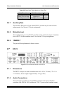
2.7.3 Video Reference
A composite video signal should be connected to the video ref. BNC connector using
a 75Ω shielded cable. There is a loop-through connection that will require a 75Ω
termination if this facility is not being used.
2.7.4 LTC Output
After de-multiplexing time-code information from the Dolby E stream, the DP572
provides a standard SMPTE LTC output.
2.7.5 Serial I/O (Remote)
Future versions of the DP572 will allow remote control via the front-panel (RS-232)
or rear-panel (RS-485) ports. See Section 6.4 for further information. The serial I/O
connections can also used for software upgrades.
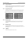
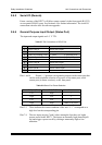
2.7.6 General Purpose Input/Output (Status Port)
The input and output signals are 0–5 V TTL.