


Dolby Installation Guidelines Unit Connections and Dimensions
2-2
the User button for three seconds. The LED on the User button will illuminate when
the user option is selected. This option is only available in version 2.5 or later of the
unit software. See Section 6.4 for further information.
The DP562 communicates at 9.6 kbps and has a fixed unit address of 8282.
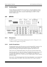
2.2.2 Status Activity and Remote Level Control
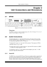
The Status/Remote connector on the rear panel allows remote monitoring of the status
output activity and remote control of the analog output level. When the remote level
control is enabled, the internal master level control is disabled.
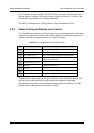
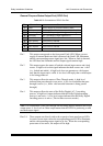
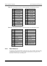
Table 2-1 Pin Connections for Status/Remote Port
Pin Connection Comments
1
Fault Processor/memory fault
2
AC-3/PCM 1 = AC-3 bitstream; 0 = Non AC-3
3
AC-3 CRC Error AC-3 CRC error encountered during decode
4
AC-3 CRC Error (+5 V)
Pin 3 and pin 4 is closed for 100 ms when a
CRC error is detected
5
Ground (and pot “low”)
6
Pot wiper Controls remote level
7
Pot “hi”
8
Remote LED 1 = Remote Fader selected
9
Remote Switch Select Remote Fader
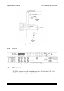
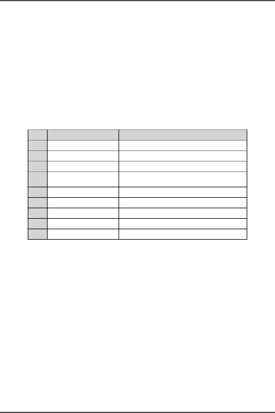
The table above contains details of the pin connections for the Status/Remote port. The
test box shown in the figure below can be used as an example for monitoring
Status/Remote port activity and controlling the analog output level remotely. A 10kΩ
potentiometer is often used for the remote level control.