


Dolby Installation Guidelines Unit Connections and Dimensions
2-6
The DP569 can communicate at rates of 9.6, 19.2, or 38.4 kbps. The unit address can
be any discrete tributary address as specified in SMPTE RP 113-1996. See Section
6.4 for further information.
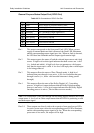
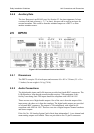
2.4.7 General Purpose I/O
The GP I/O ports on the DP569 have female 9-pin D-connectors, and operate at 5 V
CMOS output levels.
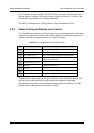
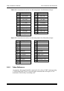
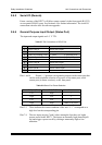
General Purpose Status Input Port (GP I/O In)
Table 2-2 Pin Connections of GPI/O In Port
Pin Connection Comments
1
Bypass Select Bypass Input as source for Switched Output
2
Autodetect Autodetect and pass-through valid AC-3 signals
3
Pre-encoded Force Pass-Through mode (no AC-3 encoding)
4
PCM Force AC-3 encoding (no Pass-through mode)
5
User Preset 1 Select User Preset 1
6
User Preset 2 Select User Preset 2
7
User Preset 3 Select User Preset 3
8
User Preset 4 Select User Preset 4
9
Ground
Pin 1 Connecting pin 1 to ground (pin 9) will place the unit into Bypass mode.
This will occur regardless of the setting of the Bypass mode parameter in
the I/O control menu. However, enabling bypass in the menu will also
place the unit into bypass, regardless of the presence of this connection.
Pins 2–4 In order to select one of these modes, a high-to-low transition should be
placed on a pin. The input format corresponding to the pin will be
selected, as long as the selection does not conflict with another setting
(such as clock source). As only one of these settings can be selected, the
input formats will be active in the order that they are selected. A low-to-
high transition on these pins will not have any effect.
Pins 5–8 These operate in the same way as pins 2–4. The relevant preset will be
recalled immediately if a high-to-low transition occurs. If pin 1 is
grounded, then bypass operation will be active irrespective of the setting
of Bypass mode within the preset.