


Dolby Installation Guidelines Unit Connections and Dimensions
2-12
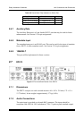
2.6.5 Serial I/O (Remote)
Future versions of the DP571 will allow remote control via the front-panel (RS-232)
or rear-panel (RS-485) ports. See Section 6.4 for further information. The serial I/O
connections can also used for software upgrades.
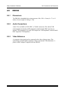
2.6.6 General Purpose Input/Output (Status Port)
The input and output signals are 0–5 V TTL.
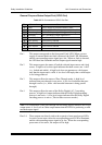
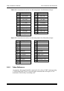
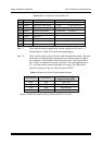
Table 2-7 Pin Connections of GPI/O Port
Pin Connection Comments
1
Preset Tally A Preset tally output
2
Reference Video Valid 1: Valid; 0: Ref video error
3
Dolby E Encoding Valid 1: Valid; 0: Encoding error
4
System Operational 1: Functional 0: Failed
5
Fault 1: Functional 0: Hardware Fault
6
Preset Tally B Preset tally output
7
Preset Ctrl A Preset control input
8
Preset Ctrl B Preset control input
9
Ground —
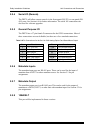
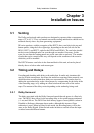
Pins 1 and 6 Presets 1–3 generate corresponding outputs on the status port that
can be used to indicate selection of a preset via the status port, serial
remote port (in future versions), or the front panel.
Table 2-8 Status Port Preset Selection
Preset Tally A (Pin 1) Preset Tally B (Pin 6) Preset
Low High 1
High Low 2
Low Low 3
High High Other or no preset
Pins 2-5 These indicate the current condition of the unit. A “1” corresponds to a
high level on the corresponding pin.
Pins 7-8 The two inputs on pins 7 and 8 select among the first three (of eight)
presets stored in the DP571. The inputs are normally high (internal pull-
up) and trigger a preset recall by sensing a momentary high-to-low
transition.