


Dolby Installation Guidelines Unit Connections and Dimensions
2-9
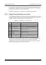
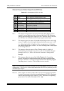
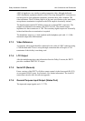
Table 2-4 Pin Connections for the Cat. No. 548 Analog Option Card Multichannel Output
Pin Connection
Pin Connection
1
Bsr + Out
14
Bsr - Out
2
Bsr Ground
15
Bsl + Out
3
Bsl – Out
16
Bsl Ground
4
Rs + Out
17
Rs - Out
5
Rs Ground
18
Ls + Out
6
Ls – Out
19
Ls Ground
7
Subwoofer + Out
20
Subwoofer - Out
8
SW Ground
21
Center + Out
9
Center – Out
22
C Ground
10
Right + Out
23
Right - Out
11
R Ground
24
Left + Out
12
Left – Out
25
L Ground
13
—
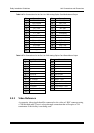
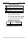
Table 2-5 Pin Connections for the Cat. No. 548 Analog Option Card Stereo/Mono Output
Pin Connection
Pin Connection
1
Digital Ground
14
—
2
—
15
—
3
—
16
—
4
—
17
—
5
—
18
Solo In R +
6
Solo In R -
19
SR Ground
7
Solo In L +
20
Solo In L -
8
SL Ground
21
Mono + Out
9
Mono – Out
22
M Ground
10
Right Stereo + Out
23
Right Stereo – Out
11
R Ground
24
Left Stereo + Out
12
Left Stereo - Out
25
L Ground
13
—
2.5.3 Video Reference
A composite video signal should be connected to the video ref. BNC connector using
a 75Ω shielded cable. There is a loop-through connection that will require a 75Ω
termination if this facility is not being used.