


9
ENGLISH
!6
RS232C/RS422A selector switch
• Use this to switch the serial remote connector signal between
RS232C and RS422A according to the external controller’s
signal.
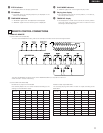
!7
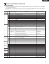
RS232C/RS422A connector
• This is a serial remote connector. A personal computer or
other external controller can be connected to control the DN-
M991R externally.
• Applicable connector: 9-pin D-sub (female)
• Baud rate: 9600 bps or 19200 bps
• Pin layout:
@2
IN LEVEL L/R controls
• Use these controls to adjust the level of the audio signals from
the ANALOG IN connectors.
@3
OUT LEVEL L/R controls
• Use these controls to adjust the level of the audio signals from
the ANALOG OUT connectors.
@4
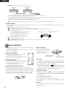
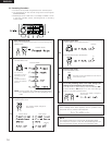
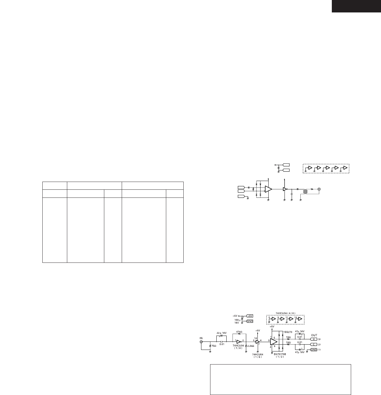
DIGITAL OUT (AES/EBU) connector
• This is an active balanced output using an XLR type connector.
• Connect this connector to the balanced digital input connector
on an amplifier or console.
• Signal format: AES/EBU or SPDIF.
• Pin layout: 1. Common
2. Cold
3. Hot
• Applicable connector: Cannon XLR-3-31 or equivalent.
• This unit uses a balanced digital output. A conversion circuit is
necessary for connection to an unbalanced circuit.
Example of balanced/unbalanced conversion circuit.
CUE WRITE (REC, Edit mode)
• Press this button during the standby, pause, play, or manual
search. When the edit mode and recording mode to record a
cue signal.
!5
EJECT button
• Press this button to eject the cartridge.
• The cartridge cannot be ejected during recording or while the
UTOC is being written.
+5V
GND
OUT
75Ω
33µ 16V
+
+
33
4
86
5
4
7
14
11
931
74HCU04
( 1 / 6 )
74HCU04 ( 4 / 6 )
SN75157
( 1 / 2 )
110Ω
1SS270
+5V
+5V
100µ
16V
100µ
16V
+
+5V
H
C
GND
( )
3
( )
2
( )
1
IN
100P
5 : 1
13
Pin No.
1
6
2
7
3
8
4
9
5
Signal name
NC
NC
T
x
D
NC
R
x
D
NC
NC
NC
S.GROUND
I/O
–
–
O
–
I
–
–
–
–
I/O
–
–
O
O
I
I
–
–
–
Signal name
NC
S.GROUND
T
x
D (RETURN)
T
x
D
R
x
D
R
x
D (RETURN)
NC
NC
NC
RS422A
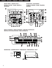
(2) Rear Panel
RS232C
!8
TERMINATOR switch
• When set to the “ON” side, the serial remote connector’s pins
are terminated internally.
!9
KEYBOARD connector
• To use a keyboard, connect it to this connector.
• The connector is a mini DIN type 6-pin connector.
@0
ANALOG IN connectors
• These are active balanced inputs using XLR type connectors.
• Connect these connectors to the balanced analog output
connectors on an amplifier or console.
• Pin layout: 1. Common
2. Hot
3. Cold
• Applicable connector: Cannon XLR-3-32 or equivalent.
@1
ANALOG OUT connectors
• These are active balanced outputs using XLR type connectors.
• Connect these connectors to the balanced analog input
connectors on an amplifier or console.
• Pin layout: 1. Common
2. Hot
3. Cold
• Applicable connector: Cannon XLR-3-31 or equivalent.
NOTE: Do not short-circuit the hot or cold pin with the common
pin.
TO
DN-991R
DIGITAL
OUT
@5
MONITOR jack
• Connect headphones with an impedance of 30 to 40 Ω/ohms.
@6
DIGITAL IN (AES/EBU) connector
• This is an active balanced input using an XLR type connector.
• Connect this connector to the balanced digital output
connector on an amplifier or console.
• Signal format: AES/EBU or IEC958 Type I
• Pin layout: 1. Common
2. Cold
3. Hot
• Applicable connector: Cannon XLR-3-32 or equivalent.
• This unit uses a balanced digital input. A conversion circuit is
necessary for connection to an unbalanced circuit.
Example of unbalanced/balanced conversion circuit.
TO
DN-991R
DIGITAL
IN
WARNING:
Turn PITCH control OFF when making digital recording.
Most digital recorders will not accept a variable pitched
digital signal.
@7
POWER switch
• This turns the set on and off.
@8
AC inlet
• Connect the included power cord here.