


10
ENGLISH
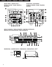
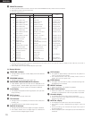
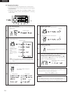
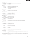
(3) Display Window
#0
TRACK NO. indicator
• This lights When the track number display shows the selected
track number.
#1
PROGRAM indicator
• This lights when the Program play mode is set.
#2
DISC NAME/TRACK NAME/DATE indicators
• “DISC NAME” lights when the disc name is displayed on the
character display, “TRACK NAME” lights when the track name
is displayed, and “DATE” lights when the date is displayed.
#3
Level display
• This displays the playback level during playback, the input level
during recording.
#4
EDIT indicator
• This lights when the edit mode is set.
#5
TOC indicator
• This lights when it is necessary to rewrite the TOC (UTOC) due
to editing, etc
• This flashes while the TOC (UTOC) is being written.
#6
DIGITAL IN indicator
• This lights (or flashes) when the digital input signal is selected.
• The indicator flashes when the digital signal is unlocked and
remains lit when the digital signal is locked.
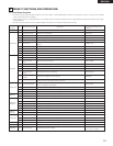
NOTES:
• The tally output pin has open collector IC specifications (Imax. 20 mA, Vmax. 5 V), but the maximum supply current is 80 mA, so use with a
total load current of 80 mA or less.
• 13 Pin enable when Hot start (Preset 36)) set up off mode.
Pin No.
1
14
2
15
3
16
4
17
5
18
6
19
7
20
8
21
9
22
10
23
11
24
12
25
13
Signal name
I/O
Level
FG
PLAY CODE 1 tally
PLAY CODE 1 command
PLAY CODE 2 tally
PLAY CODE 2 command
PLAY CODE 3 tally
PLAY CODE 3 command
PLAY CODE 4 tally
PLAY CODE 4 command
Tally common
PLAY CODE 5 command
REPEAT command
STOP command
REPEAT tally
LOAD command
LOAD tally
FADER START command
Tally power supply
FADER START return &
Command common
Reserved
Reserved
Reserved
Reserved
Hot Start ON (Low)
–
O
I
O
I
O
I
O
I
–
I
I
I
O
I
O
I
–
–
–
–
O
–
O
I
TTL (lol=20 mA)
HCMOS (li–3 mA)
TTL (lol=20 mA)
HCMOS (li–3 mA)
TTL (lol=20 mA)
HCMOS (li–3 mA)
TTL (lol=20 mA)
HCMOS (li–3 mA)
HCMOS (li–3 mA)
HCMOS (li–3 mA)
HCMOS (li–3 mA)
TTL (lol=20 mA)
HCMOS (li–3 mA)
TTL (lol=20 mA)
PHOTO COUPLER
+5 V, 20 mA
(li=10 mA)
DRY CONTACT
DRY CONTACT
HCMOS (li–3 mA)
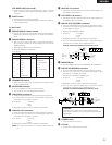
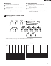
@9
REMOTE connector
• This is a parallel remote connector. Use it to control the DN-M991R with dry contact circuit connections.
• Applicable connector: 25-pin D-sub (male)
• Connector signal layout:
Signal name
FG
PLAY tally
PLAY command
PAUSE tally
PAUSE command
STDBY/CUE tally
STDBY/CUE command
END CUE tally
TRACK (+) command
Tally common
TRACK (–) command
REC command
SEARCH (FWD) command
CUE tally
SEARCH (REV) command
REC tally
FADER START command
Tally power supply
Command common
Command common
REC E.O.M.
E.O.M. tally
Reserved
E.O.M. tally
Hot Start OFF (High)
Hot Start OFF
I/O
–
O
I
O
I
O
I
O
I
O
I
I
I
O
I
O
–
O
–
–
–
–
–
–
–
#7
CUE indicator
• This lights for approximately 3 seconds when the position at
which a cue signal is set is played.
• The indicator flashes when the standby mode is set at a
position at which a cue signal is set.
#8
EOM indicator
• This lights when the EOM is preset, and starts flashing when
the EOM set time is reached.
#9
REPEAT indicator
• When this indicator is lit, playback is repeated.
$0
EJECT LOCK indicator
• When this indicator is lit, the eject lock function is set and the
cartridge is not ejected even when the eject button is pressed.
$1
Character display
• This displays disc names, track names and the date.
• Various instructions are displayed here during presetting,
programming, editing, etc.
$2
NEXT No. display
• This displays the number of the next track to be played.
• The program number is displayed during program input and
editing.
• During recording, this indicates the digital input signal’s
sampling frequency.
• When the playback pitch is changed, the pitch value flashes for
3 seconds.
Hot Start ON