


4
ENGLISH
4
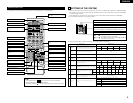
FEATURES
1. Multi Room Music Entertainment System
Multi Source Function:
This unit’s Multi Source function lets you select
different audio or video sources for viewing or
listening Different sources can thus be enjoyed
in the main room and the subroom
simultaneously.
2. Dolby Pro Logic II decoder
Dolby Pro Logic II is a new format for playing
multichannel audio signals that offers
improvements over conventional Dolby Pro Logic.
It can be used to decode not only sources
recorded in Dolby Surround but also regular stereo
sources into five channels (front left/right, center
and surround left/right). In addition, various
parameters can be set according to the type of
source and the contents, so you can adjust the
sound field with greater precision.
3. Dolby Digital
Using advanced digital processing algorithms,
Dolby Digital provides up to 5.1 channels of wide-
range, high fidelity surround sound. Dolby Digital
is the default digital audio delivery system for
North American DVD and DTV.
4. DTS (Digital Theater Systems)
DTS provides up to 5.1 channels of wide-range,
high fidelity surround sound, from sources such as
laser disc, DVD and specially-encoded music
discs.
5. DTS-ES Extended Surround and DTS Neo:6
The AVR-2802 is compatible with DTS-ES Extended
Surround, a new multi-channel format developed by
Digital Theater Systems Inc.
The AVR-2802 is also compatible with DTS Neo:6, a
surround mode allowing 6.1-channel playback of
regular stereo sources.
6. Component Video Switching
In addition to composite video and “S” video
switching, the AVR-2802 provides 2 sets of
component video (Y, P
B
/CB, PR/CR) inputs for the
DVD and TV/DBS inputs, and one set of
component video outputs to the television, for
superior picture quality.
7. Video Select Function
Allow you to watch one source (visual) while
listening to another source (audio).
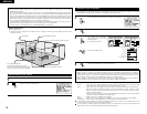
• Do not plug in the AC cord until all connections
have been completed.
• Be sure to connect the left and right channels
properly (left with left, right with right).
• Insert the plugs securely. Incomplete connections
will result in the generation of noise.
• Use the AC OUTLET for audio equipment only.
Do not use them for hair driers, etc.
• Note that binding pin plug cords together with AC
cords or placing them near a power transformer
will result in generating hum or other noise.
• Noise or humming may be generated if a
connected audio equipment is used independently
without turning the power of this unit on. If this
happens, turn on the power of the this unit
.
Connecting the audio components
5
CONNECTIONS
R
L
R
L
R
INPUT OUTPUT
LRL
R
OUTPUT
L
R
L
INPUT
OPTICAL COAXIAL
OUTPUT
OPTICAL
L
R
L
R
L
R
L
R
OUTPUT
DIGITAL AUDIODIGITAL AUDIO
DIGITAL AUDIODIGITAL AUDIO
B
B
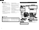
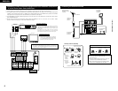
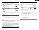
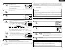
CD player
Connecting a CD player
Connect the CD player’s
analog output jacks
(ANALOG OUTPUT) to this
unit’s CD jacks using pin
plug cords.
Connecting a turntable
Connect the turntable’s output cord to the
AVR-2802’s PHONO jacks, the L (left) plug to
the L jack, the R (right) plug to the right jack.
NOTES:
• This unit cannot be used with MC
cartridges directly. Use a separate head
amplifier or step-up transformer.
• If humming or other noise is generated
when the ground wire is connected,
disconnect the ground wire.
Turntable
(MM cartridge)
Ground
wire
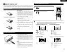
Use these jacks if you wish to connect external power
amplifier(s) to increase the power of the front, center,
surround and surround back sound channels, or for
connection to powered loudspeakers.
To use Surround back with one speaker, connect the
speaker to SURR. BACK L CH.
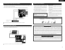
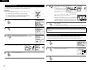
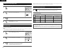
MD recorder, CD recorder or other component
equipped with digital input/output jacks
CD player or other component equipped
with digital output jacks
Connecting the DIGITAL jacks
Use these for connections to audio equipment with digital output. Refer to
page 13 for instructions on setting this terminal.
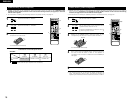
Connecting a tape deck
Connections for recording:
Connect the tape deck’s recording input jacks (LINE IN or REC) to this unit’s
tape recording (CDR/TAPE OUT) jacks using pin plug cords.
Connections for playback:
Connect the tape deck’s playback output jacks (LINE OUT or PB) to this
unit’s tape playback (CDR/TAPE IN) jacks using pin plug cords.
CD recorder or Tape deck
• When making connections, also refer to the operating instructions of the other components.
The power to this outlet is turned on and off when the power is switched between on and standby from the
remote control unit or power switch.
NOTES:
• Use 75 Ω/ohms cable pin cords for coaxial connections.
• Use optical cables for optical connections, removing the cap before
connecting.
Power supply cord
AC 230V, 50Hz
Connecting the AC OUTLET
AC OUTLET
• SWITCHED
(total capacity – 100 W)
The power to this outlet is turned on and off in conjunction with the
POWER operation switch on the main unit, and when the power is
switched between on and standby from the remote control unit.
No power is supplied from this outlet when this unit’s power is at
standby. Never connect equipment whose total capacity is above 100
W.
NOTE:
Only use the AC OUTLET for audio equipment. Never use them for
hair driers, TVs or other electrical appliances.
Route the connection cords, etc., in
such a way that they do not
obstruct the ventilation holes.
NOTE:
If humming noise is generated
by a tape deck, etc., move the
tape deck away.
Connecting the pre-out jacks